PCB assembly with metal case.
Typical Metal enclosures: stainless steel, aluminums,
Production process type: metal stamping, die casting,
Following is a case study.

Assembly of the module IPU
Prerequisites
To begin the assembly, you must have:
– A PCB card type IPU (length 80 mm) assembled (see document GUIDE 3: ASSEMBLY OF THE
PCB CARD TYPE IPU)
– A Nanopi NEO plus 2 already prepared (see document GUIDE 1: ASSEMBLY AND INSTALLATION OF THE NANOPI)
– An enclosure of length 80 mm
– A cover plate type 1
– A cover plate type 2
– 8 screws M3*8 T10 black color
– A rivet diameter 3.2 mm, length 16 mm
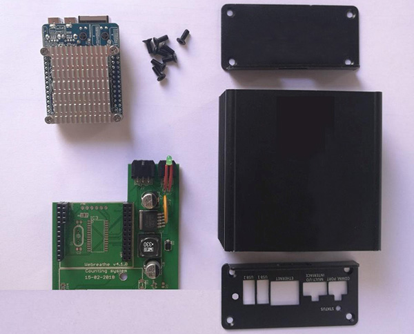
Figure 1: Necessary components
1. Nanopi
Plug the Nanopi on the PCB card
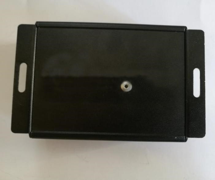
2. Enclosure
1) Take the enclosure
2) Make a hole diameter 4 mm at the coordinates indicated on the picture
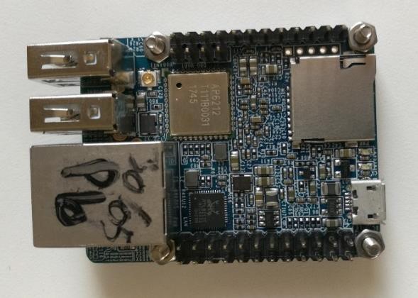
Figure 2: Nanopi NEO Plus 2
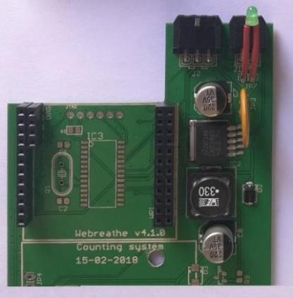
Figure 3: PCB card type IPU
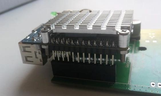
Figure 4: Plug the Nanopi on the PCB card
3) Place the cover plate type 2 and maintain it in position using four screws M3*8 T10 black color
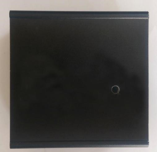
Figure 5: Make a hole diameter 4 mm
Enclosure 80 mm
Cover plate type 2
Screw M3*8 T10
black color
Diameter 4 mm
37.3 mm
22.9 mm
4) Insert the PCB card in the second slot of the enclosure
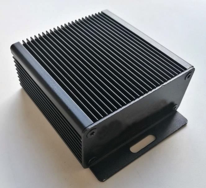
Figure 6: Place the cover plate type 2
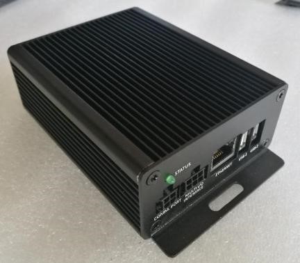
5) Take the cover plate type 1 and place it at the other side of the enclosure
NOTE: Place the flashing LED first
6) Maintain the cover plate with four screws M3*8 T10 black color
WARNING: Respect the direction shown in figure 9. Else, you will not be able to use the rivet.
Figure 10: Place the cover plate type 1
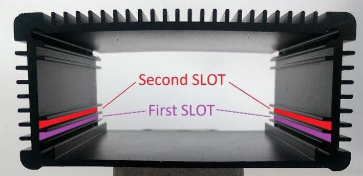
Figure 7: Insert the PCB card in the second slot of the enclosure (1)
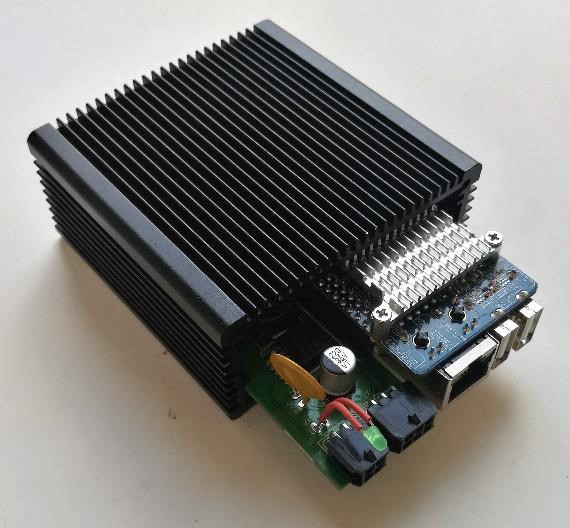
Figure 8: Insert the PCB card in the second slot of the enclosure (2)
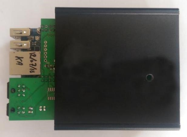
Figure 9: Insert the PCB card in the second slot of the enclosure (3)
Cover plate type 1
3. Rivet
1) Take the assembled module
2) Place the rivet inside the hole of the enclosure
3) Use the rivet
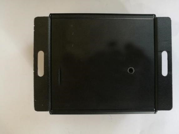
Figure 11: Take the assembled module
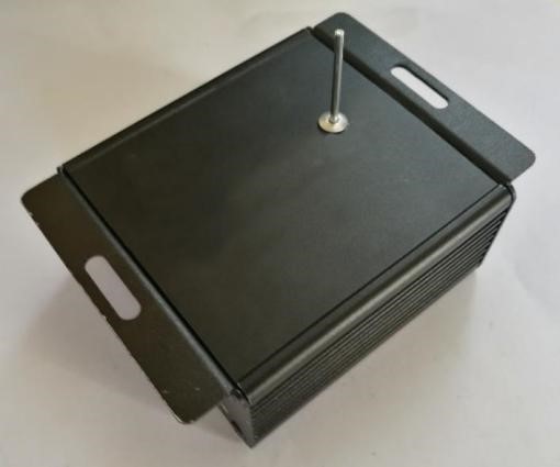
Figure 12: Place the rivet