Printed circuit boards (PCBS) are widely used in a variety of electronic devices, whether it is mobile phones, computers, or complex machines, you can find circuit boards. If the PCB or PCBA has defects or manufacturing problems, the final product may malfunction and cause inconvenience. In these cases, manufacturers will have to recall the devices and spend more time and resources to fix the fault.
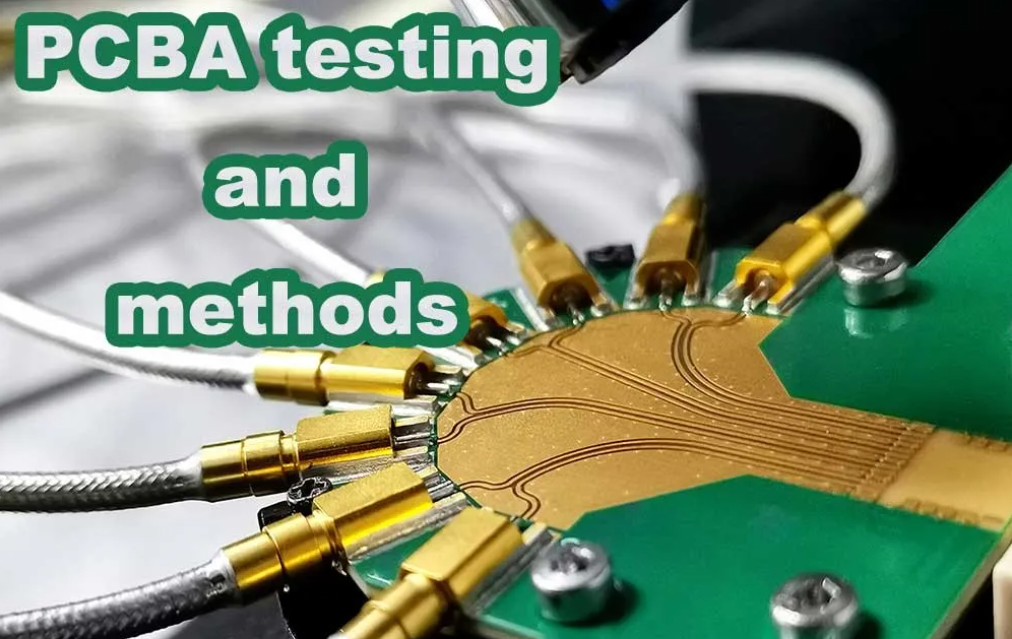
Therefore, PCBA testing has become an integral part of the circuit board manufacturing process, which finds problems in time, assists the staff in dealing with them quickly, and ensures the high quality of the PCBA. Let’s understand the 14 commonly used test methods of PCB.
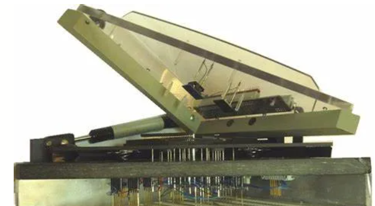
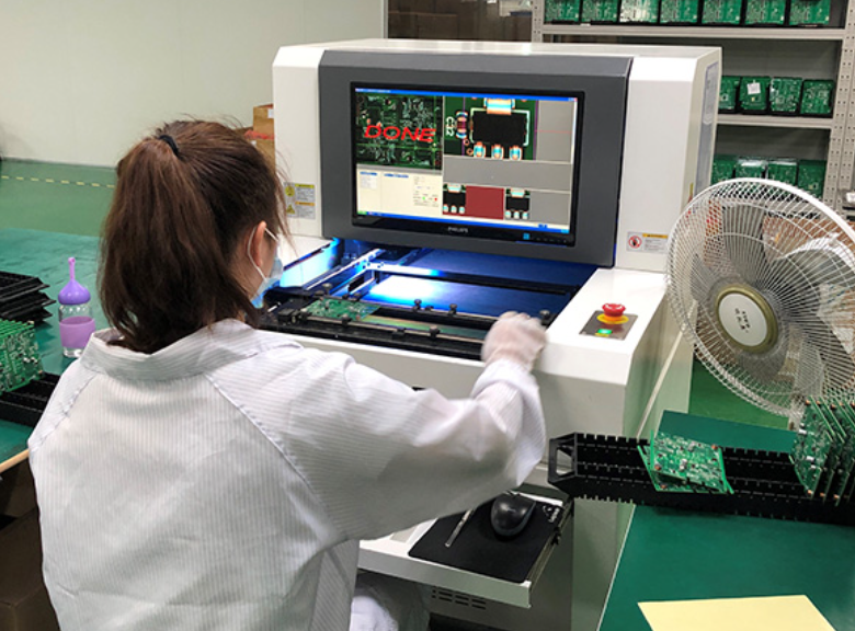
1. Online Testing (ICT)
ICT, that is, automatic online testing, is a modern PCB manufacturer must test equipment, very powerful. It is mainly through the test probe to contact the test point of the PCB layout to detect the PCBA line open circuit, short circuit, and fault of all parts, and inform the staff.
ICT has a wide range of uses, high measurement accuracy, and clear indications of detected problems, making it easy for even workers with average electronic skills to deal with problematic PCBA. The use of ICT can greatly improve production efficiency and reduce production costs.
2. Flying Probe testing
Flying Probe(Flypin) testing and in-line testing (ICT) are both highly recognized and effective forms of testing, both of which can be effective in identifying production quality issues, but Flying Probe testing is proving to be a particularly cost-effective way to improve board standards. In contrast to traditional testing methods, which place the test probes in a fixed position, flying needle testing uses two or more independent probes that run without a fixed test point.
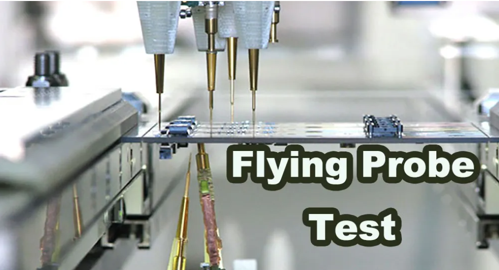
These probes are electromechanical controlled and move according to specific software instructions. Therefore, the initial cost of flying needle testing is low, and it can be done by modifying the software without changing the fixed structure. In contrast, the initial fixture cost of ICT is higher, so flying needle testing is cheaper for small batch orders, but ICT is faster and less error-prone than flying needle testing, so ICT is still more cost-effective for large batch orders.
3. Functional Test
Functional system test using the special test equipment in the middle and end of the production line to conduct a comprehensive test of the functional modules of the circuit board to confirm the quality of the circuit board. There are two main types of functional testing: Final Product Test and Hot Mock-up.
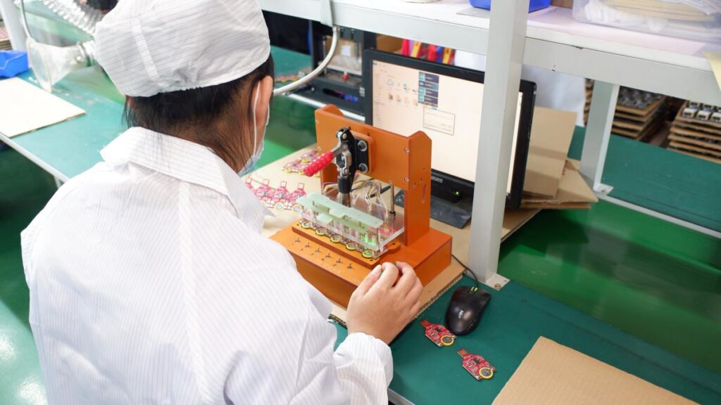
Functional testing is the most efficient testing method in mass production. The customized fixture simulates the use of device environment so that workers can quickly judge whether the product is qualified as a user. It is worth mentioning that functional testing is usually performed in conjunction with burning to ensure that the firmware of the product is also working properly.
4. Automated Optical Inspection (AOI)
AOI uses a single 2D camera or two 3D cameras to take a picture of the PCB and then compares the board photo with a detailed schematic. If the circuit board does not match the schematic to a certain extent, the mismatch of the circuit board will be marked for inspection by technicians, and AOI can detect the fault in time. However, AOI inspection does not power the circuit board and cannot detect 100% of all component problems, so AOI is generally used in combination with other test methods, commonly used test combinations are:
● AOI and fly needle
● AOI and online testing (ICT)
● AOI and functional testing
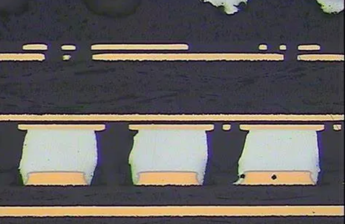
5. X-ray testing
X-ray testing, it uses low-energy X-rays to quickly detect the circuit board open circuit, short circuit, air welding, welding and other problems.
X-ray is mainly used to detect ultra-fine pitch and ultra-high density defective circuit boards, as well as defects such as bridging, chip missing, and dislocation generated during assembly. It can also use tomography to detect internal defects in IC chips. This is the only way to test the bonding quality of the ball grid array and the solder ball. The main advantage is that BGA solder quality and embedded components can be checked without the cost of fixed fixtures.
6. Laser inspection
This is the latest development in PCB testing technology. It scans the printed board with a laser beam, collects all the measurement data, and compares the actual measurement values to the preset accepted limits. The technology has been validated on bare boards and is being considered for assembly board testing. That’s more than enough speed for a mass production line. Fast output, no fixture, visual smooth is its main advantage; High initial cost, maintenance and usage problems are the main disadvantages.
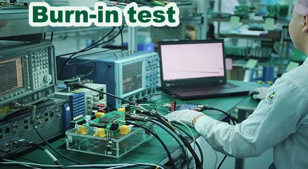
7. Aging test
Aging test refers to the process of simulating the various factors involved in the actual conditions of use of the product to carry out the corresponding condition enhancement experiment. The purpose is to test the stability and reliability of the product in a specific environment.
According to the design requirements, the product is placed under specific temperature and humidity conditions, continuous simulation work for 72 hours to 7 days, record the performance data, and reverse the production process for improvement to ensure that its performance meets the market demand. Burn-in testing usually refers to electrical performance testing, similar to drop testing, vibration testing, salt spray testing, etc.
8. Solderability testing
It ensures a strong surface and increases the chances of forming a reliable solder joint. Solderability testing, or “solderability” in English. It refers to a qualitative and quantitative evaluation of the weldability of components, PCB boards, pads, solders and fluxes through the principle of wetting balance.
9. PCB Contamination test
The ion contamination of PCB refers to the ion contamination from the flux residue, chemical cleaning agent residue, air humidity, electroplating, wave soldering, reflow welding and other processes on the surface of PCBA circuit boards. PCN contamination detects large amounts of ions that can contaminate boards, causing corrosion and other problems.
10. Slice analysis
To investigate defects, open circuits, short circuits and other faults.
11. TDR test
When the fault of high-speed or high-frequency board is found, it is recommended to use TDR to test and analyze, so that you can quickly determine whether there is an on/off circuit and determine the fault location.
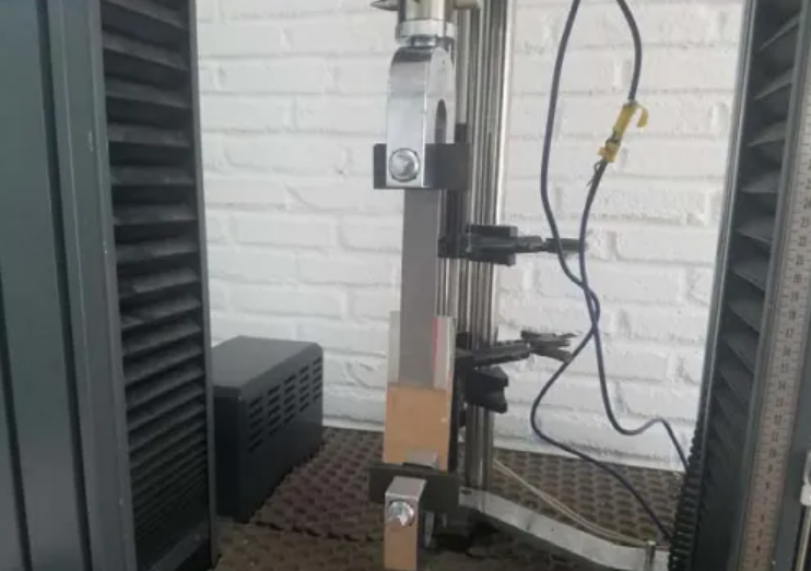
12. Stripping test
PCB stripping strength test generally refers to the bond strength test between copper foil and substrate or copper foil and brown film. Evaluate the bonding strength between PCB copper foil and substrate after receiving state, after thermal stress, after high temperature state, etc.
13. Float welding test
To determine the level of thermal stress that PCB holes can resist. This test is suitable for float welding of coated holes, surface conductors and pads. The scum and flux residue on the surface of the solder should be thoroughly removed before the test. The sample is then slid onto the molten solder for a floating time of up to 5 minutes, so that the depth of immersion of the sample in the molten solder does not exceed 50% of the sample thickness. After the residence time is reached, the sample is removed from the solder. Hold the sample level until the solder solidifies.
14. Wave Soldering test
This test is suitable for wave soldering of coated holes, surface conductors and pads. Set and record relevant parameters: splint mode (if required), transfer speed, preheating, welding device with or without anti-oxidation oil, equipment process control, tilt Angle, plate preheating temperature and welding temperature. PCBA testing is an integral part of ensuring the quality of product delivery. It determines the performance of the product, controls the quality of the product, and reduces the after-sales and maintenance rate.