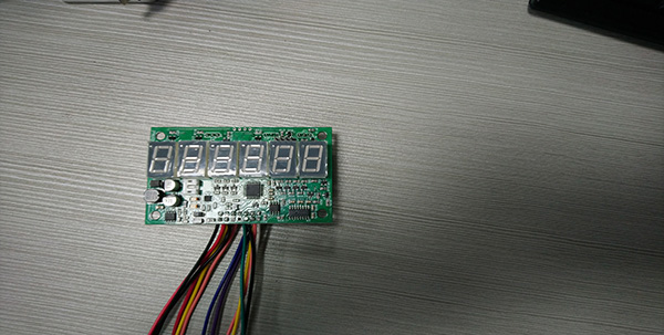
We make many boards with wires installed, usually customers would just need to install our PCBA with wires on their boxes, then a completed product done.
Case Study:
Customer: Brail
Board: PWREII
Board function: communication boards.
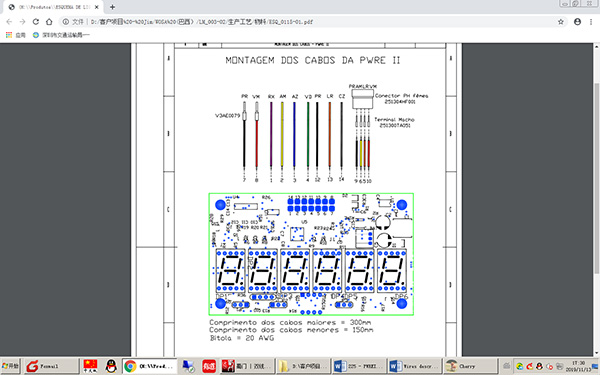
Customer uses our boards to be installed on a large machine. we have made boards with all wires installed. 14 wires on each board. the customer can easily install on the machine, saving a lot of efforts at customer side.
Wires on PCBAs, with LEDs.
14 wires are soldered on each PCBA.
So, how to solder all 14 wires efficiently and effective. Initially wires were soldered manually but it was slow. Fumax engineers designed a special fixture which will allow wires to be soldered by wave soldering machines. customer is extremely happy with the results.
| PIN | COLOR | REFERENCE | DESCRIPTION |
| 1 | Purple | TX+ 485 | RS485 Communication |
| 2 | Yellow | TX 232 | RS232 Communication |
| 3 | Blue | UART RX | RX TTL Communication |
| 4 | Green | UART TX | TX TTL Communication |
| 5 | Orange (short) | S2 | HALL S2 |
| 6 | Yellow (short) | S1 | HALL S1 |
| 7 | Black | GND | Source pin negative |
| 8 | Red | 24v | Source pin positive |
| 9 | Black (short) | GND sensors | HALL – |
| 10 | Red (short) | 5v | HALL + |
| 11 | NC | NC | NC |
| 12 | Black | GND serials | RS232 – |
| 13 | Orange | RX 232 | RS232 Communication |
| 14 | Grey | TX- 485 | RS485 Communication |
Boards testing procedures:
1. Abstract
This document aims to standardize the tests in the manufacture of PWREII.
Note: Cables that do not have connectors must be pickled in 1cm for the tests to be carried out and after the test, they must be cut off so that the cable is isolated.
2. Jumpers Configuration
JP1 (1 and 2) enables display 1
JP3 (1 and 2) counts in both ways.
JP2 (1 and 2) reset counting.
3. Flashing the firmware
3.1. Install the file “sttoolset_pack39.exe”, available in https://drive.google.com/open?id=0B9h988nhTd8oYUFib05ZbVBVWHc.
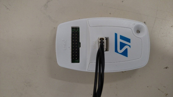
3.1. Connect the ST-Link/v2 programmer in a PC.
3.2. With the power off connect the programmer’s STM8 port on the PWREII’s ICP1 port.
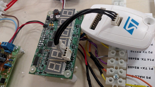
Pay attention on the pin 1 of the programmer and the board’s pin 1.
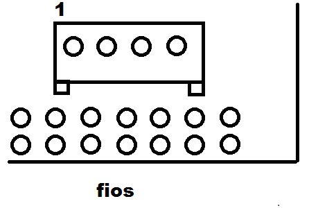
Looking from behind(where the wires comes to connector).
3.3. Power the device on
3.4. Run the ST Visual Programmer app.

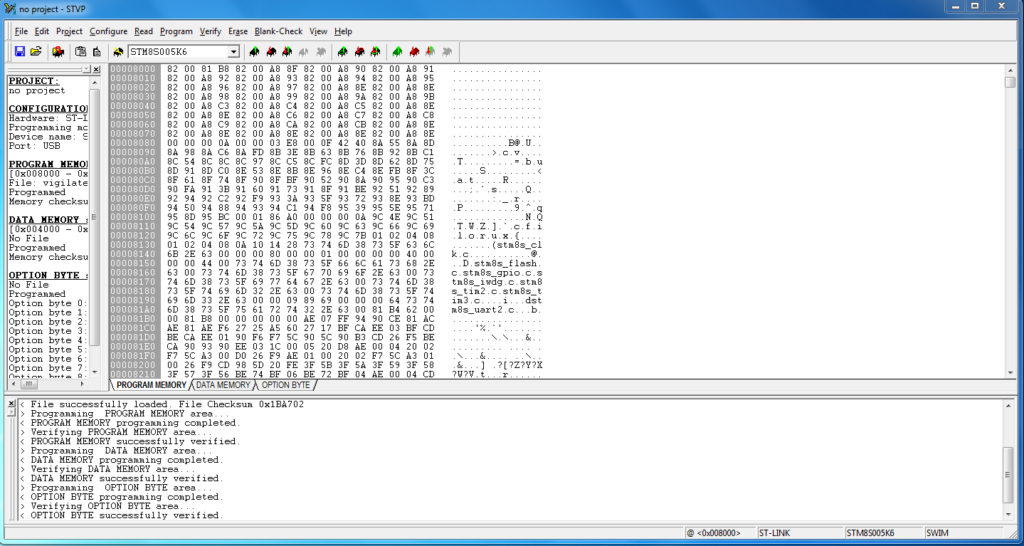
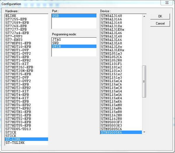
3.5. Configure like the following picture:
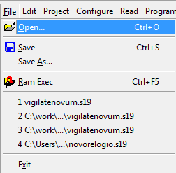
3.6. Click in File, Open
3.7. Choose the “PWREII_V104.s19” archive
3.8. Click in Program, All tabs

3.9. Check that the Firmware was programmed correctly:
3.10. Power the PWRE II off before disconnect the programmer.
4. Counting using the PWSH board (HALL Effect sensor)
4.1. Passando-se o imã da direita para a esquerda verifique que o display incrementa a contagem na direção saída.
4.2. Passando-se o imã da esquerda para a direita verifique que o display incrementa a contagem na direção de entrada.
5. RS485 Communication Test
NOTE: You will need a RS485 to USB converter
5.1. Download and install the converter driver.
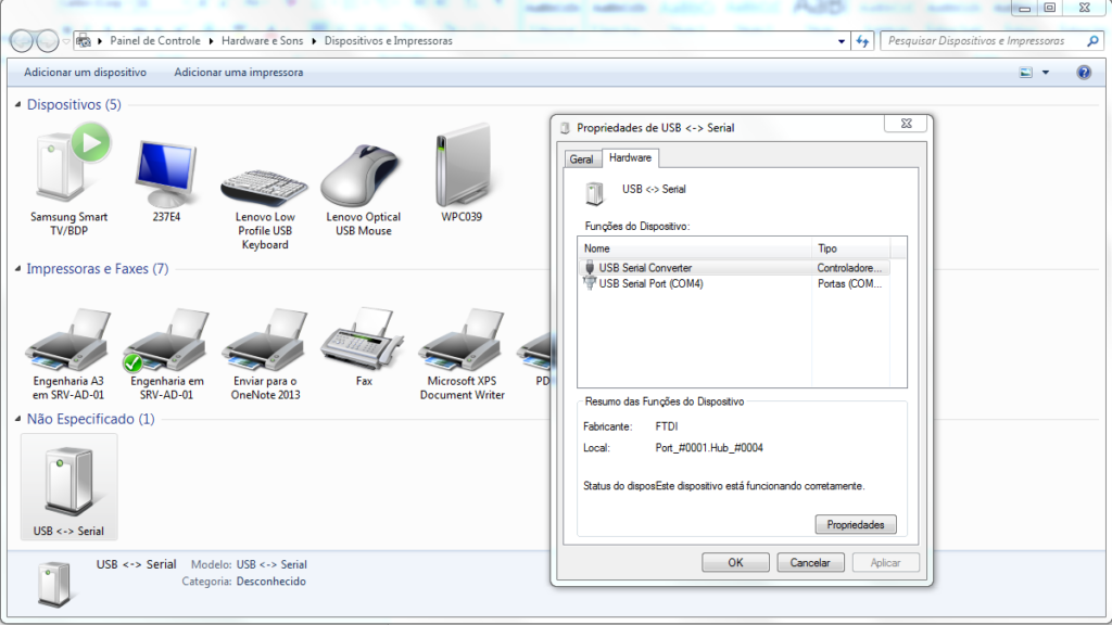
5.2. In Start menu -> Devices and printers
5.3. Check in the device properties the number of his COM port
5.4. In our case COM4.
5.5. Open the PWRE II test program available in “https://drive.google.com/open?id=0B9h988nhTd8oS1FhSnFrUUN6bW8”
5.6. Put the Serial port number and click in “abrir porta”.
5.7. Enter numeric data (6 digits per box) in the texts box next to the button “escreve contadores”. Click in this button and see that these numbers was send to the counter.
5.8. Click in “Le Contadores”, verify that the numbers in the counter ware transferred to the text box next to this button.
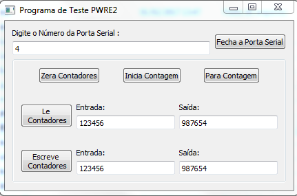
NOTE: If these tests was succeed means that both RS485 and TTL communications are working.
6. RS232 Communication test
6.1. Needed materials:
6.1.1. 1 DB9 female connector
6.1.2. 1 AWG 22 cable with 4 wires
6.1.3. 1 PC with serial port
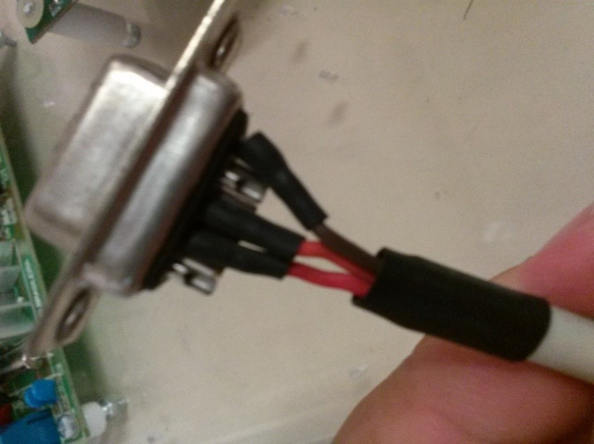
6.2. Assembly the connector like the follow image:
6.3. Connect the other side of cable on PWREII’s RS232 wires.
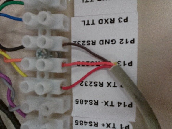
NOTE: If you have a RS232 to USB adapter you don’t need to assembly this cable.
6.4. Follow the instructions from 5.1 onwards.
7. Battery charger system test
7.1. To make this test, you must to open the battery’s red wire.
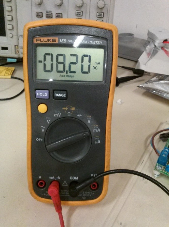
7.2. Put multimeter in series with the red wire and choose a mA scale.
7.3. Connect the positive probe in the wire that comes from PWREII and the negaive probe in the wire that goes to the battery.
7.4. Look the value on multimeter’s screen:
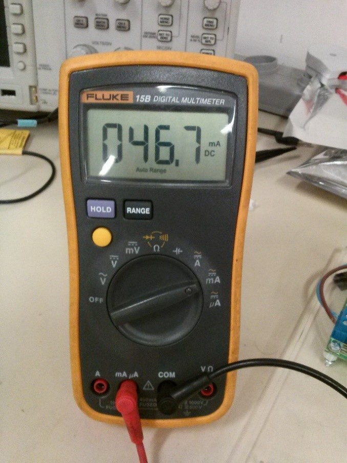
Positive value indicates that the baterry is charging.
NOTE: When the battery is is totaly empty the current rise up to 150mA.
7.5. Keep these connections and shut the power off.
