The electronic components on the PCB board have different packaging types. Although some components look the same in appearance, they are not of the same type. Their internal structures and uses are also very different. Complex electronic circuits are also made of These electronic components are composed of.
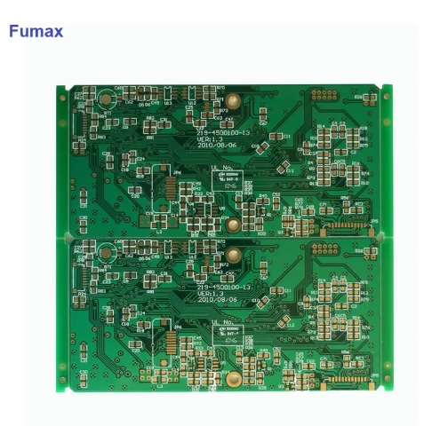
We know that there are many types of components, and the components used in circuit boards with different functions are also different, but there are always some fixed components that are commonly used. So, what are the commonly used components on PCB boards? Today, here is some simple knowledge about components to share with you!
- Resistor (referred to as resistor) Resistor is one of the most commonly used electronic components on PCB boards. It is represented by the letter R and the unit is ohms. It represents the resistance of the conductor to the current. It plays the roles of current shunting, current limiting, voltage dividing, and biasing in the circuit.
- Capacitor (referred to as capacitor) The capacitor is represented by the letter C. It is used to store charges and electric energy in the circuit. Its main feature is to pass alternating current and block direct current. The obstruction of the capacitor to the alternating current is called capacitive reactance, which is a type of reactance (the other is called inductive reactance). The size of the capacitive reactance is related to the frequency of the alternating current and its own capacity. In the circuit, capacitors mainly play the roles of coupling, filtering, resonance, bypass, compensation, frequency division, etc.
- Crystal Diode Crystal diode, represented by the letter D, is a type of semiconductor device with nonlinear volt-ampere characteristics and its main function is unidirectional conductivity. Its core part is a PN junction, which is widely used in various electronic circuits. There are many types of crystal diodes. According to their materials, they are: silicon tubes and germanium tubes; according to their functions, they are: rectification, light-emitting, detection, voltage stabilization, switching, freewheeling, rotation, Schottky diodes and silicon power diodes, etc.; According to their structural points, they are divided into contact type and planar type. The former can pass small current and the latter can pass large current.
- Inductor The inductor is represented by the letter L. Its structure is similar to that of a transformer. It is a device that converts electrical energy into magnetic energy and stores it. Its main functions in the circuit are: filtering, oscillation, delay, notch, signal screening, noise filtering, stabilizing current and suppressing electromagnetic waves. Interference etc. Inductors are also known as chokes, reactors, dynamic reactors, etc. According to their induction methods, they are divided into: self-inductance and mutual inductance. Inductors have the characteristics of direct current and resistance, that is, they prevent alternating current from passing through and allow direct current to pass smoothly. This is exactly the opposite of capacitors.
- Crystal transistor The full name of triode is semiconductor triode. It is a semiconductor device that controls current. It is a core component in electronic circuits. It is also called bipolar transistor and transistor. It has the function of current amplification. Its essence is that the triode can use small base current to generate electricity. The change amount is used to control the larger change amount of the collector current. The magnification factor is represented by the symbol “β”. The transistor is made of two PN junctions that are very close to each other on a semiconductor substrate. The two PN junctions divide the entire semiconductor into three parts. The middle part is the base area, and the two sides are the emitter area and the collector area. The arrangement is PNP and NPN.
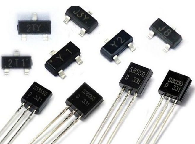
- Field effect transistor, English abbreviation FET, referred to as field effect transistor. There are two main types: JFET (junction type) and metal-oxide semiconductor field effect transistor (MOS-FET). Field effect transistor, also called unipolar transistor, is a voltage-controlled semiconductor device. It is used for amplification. Since the input impedance of the field effect tube amplifier is very high, the coupling capacitor can have a smaller capacity and there is no need to use an electrolytic capacitor.
Field effect transistors have high input impedance and are very suitable for impedance transformation. They are often used in the input stage of multi-stage amplifiers for impedance transformation. They can be used as variable resistors, constant current sources, electronic switches, etc.