Multimeter testing PCB is a common testing method used to check the functionality and reliability of printed circuit boards (PCBs). In daily life, PCB is widely used in various electronic devices, such as mobile phones, TVs, computers, etc. They are used to connect and carry electrical current so that devices can function properly.
Suppliers and manufacturers often use industrial testing methods to ensure PCB quality and reliability. These tests include functional testing, performance testing and visual inspection. In addition, some professional PCB testing service providers also provide comprehensive testing services to ensure that the quality and performance of PCB meet customer requirements.
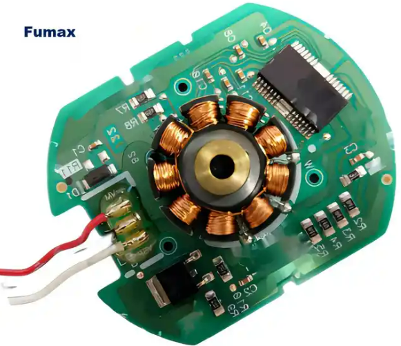
If you need to find a PCB manufacturing and PCB design manufacturer, you can contact PCB manufacturers in China. Fumax is a company that provides one-stop services for PCB design, PCB manufacturing, PCB assembly, and PCB testing.
To learn more about Chinese PCB manufacturer services, please check our website.
- What is multimeter PCB testing?
- Can a multimeter test PCB?
- What functions does a multimeter have?
- How does a multimeter work when testing PCB?
- How to test a damaged PCBA (PCB Assembly) board with a multimeter?
- What are the troubleshooting methods for PCB testing?
- Will PCB assembly and prototype PCB manufacturing factories test PCB boards?
- How to test PCB assembly function with multimeter?
- Can multimeters be used in PCB manufacturing processes?
- What automated equipment is used to test industrial manufacturing PCB or PCB assembly?
- Which method is used to test PCB boards in industrial production PCB or prototype PCB manufacturing?
- PCB manufacturing and testing factory, PCB assembly and testing manufacturer in China
What is multimeter PCB testing?
Multimeter PCB testing is a method of testing PCB (Printed Circuit Board) using a multimeter. This method is mainly used to detect open circuits and short circuits on PCBs.
When testing, you first need to visually inspect the PCB board and use a multimeter to check whether key circuits (especially power and ground) are short-circuited. Every time you solder a chip, you need to use a multimeter to measure whether the power supply and ground are short-circuited. In addition, do not swing the soldering iron around when welding to prevent the solder from being thrown onto the soldering feet of the chip (especially surface mount components), making it difficult to detect a short circuit.
Can a multimeter test PCB?
Yes, a multimeter can be used to test PCBs. However, it is important to note that great care must be taken when testing to avoid damage to the integrated circuit.
When testing flat package CMOS integrated circuits, be extra careful as any instantaneous short circuit can easily damage the integrated circuit. For example, when measuring voltage or testing waveforms with an oscilloscope probe, do not cause the test leads or probes to slip and cause a short circuit between the pins of the integrated circuit. It is best to measure on a peripheral printed circuit with direct connection to the pins.
In addition, the internal resistance of the PCB board test instrument must be large. When measuring the DC voltage of the integrated circuit pin, a multimeter with a meter head internal resistance greater than 20KΩ/V should be used, otherwise there will be a large measurement error for some pin voltages. It is also necessary to pay attention to the heat dissipation of the power integrated circuit. The power integrated circuit should have good heat dissipation and is not allowed to work at high power without a radiator. At the same time, we should also pay attention to the rationality of testing the PCB board leads.
What functions does a multimeter have?
A multimeter is a multi-functional, multi-range measuring instrument that can measure a variety of physical quantities such as AC current, AC and DC voltage, and DC resistance. Here are some of the main features of a multimeter:
- Measuring AC current: A multimeter can measure AC current. By connecting the meter in series with the circuit, the AC current in the circuit can be measured.
- Measuring DC current: A multimeter can measure DC current. By connecting the meter in parallel with the circuit, the DC current in the circuit can be measured.
- Measure AC and DC voltage: A multimeter can measure AC and DC voltage. By connecting the meter in parallel with the circuit, the AC and DC voltage in the circuit can be measured.
- Measuring resistance: A multimeter can measure resistance. By connecting an electric meter to a resistor, the resistance of the resistor can be measured.
- Measuring capacitance: A multimeter can measure capacitance, and by connecting an ammeter to a capacitor, the capacity of the capacitor can be measured.
- Measuring inductance: A multimeter can measure inductance. By connecting an electric meter to an inductor, the inductance of the inductor can be measured.
- Detect the circuit: The multimeter can detect the on-off condition of the circuit. By connecting the meter to the circuit, the on-off condition of the circuit can be detected.
- Detect the diode: The multimeter can detect the quality of the diode. By connecting the meter to the diode, the quality of the diode can be detected.
- Test the triode: A multimeter can test the performance of the triode. By connecting the meter to the triode, the performance of the triode can be tested.
A multimeter is a very practical tool that can be used to measure a variety of physical quantities and has a variety of functions and uses.
How does a multimeter work when testing PCB?
The process of using a multimeter to test a PCB is as follows:
- Prepare the test environment: Before testing, you need to prepare test instruments, test fixtures, test procedures, etc., and set up a test environment.
- Connect the test instrument to the PCB: Connect the test instrument to the PCB, either through a fixture or by directly connecting the test point.
- Execute the test program: Write the test program according to the test requirements, and test the PCB through the program-controlled test instrument.
- Test result analysis: Analyze the test results to determine whether the PCB has faults or defects.
- Repair faults: If the PCB has faults or defects, it needs to be repaired based on the analysis results and retested.
- Complete the test: If the PCB passes the test, the test work can be completed; if it fails the test, further inspection and repair are required.
It should be noted that the process of testing PCB with a multimeter needs to be adjusted and optimized according to the specific testing requirements and PCB type. At the same time, you need to pay attention to safety issues when conducting tests to avoid accidents caused by improper operation.
How to test a damaged PCBA (PCB Assembly) board with a multimeter?
The process of testing a damaged PCBA board (Printed Circuit Board Assembly) includes the following steps:
- Preliminary inspection: First, visually inspect the PCBA board to look for obvious physical damage, such as broken wires, fallen components, or obvious burn marks.
- Power supply check: Before connecting the power supply, use a multimeter to check the resistance of the power terminal to ground to confirm whether there is a short circuit. Under normal circumstances, the resistance of the power terminal to ground should be infinite.
- Functional testing: Test the functions of each circuit on the PCBA board by connecting the power supply and using appropriate testing instruments (such as multimeters, oscilloscopes, etc.). Specifically, each circuit needs to be tested to confirm that they are functioning properly.
- Load testing: After functional testing, load testing is performed to confirm the performance of the circuit under normal operating conditions. This usually involves connecting an appropriate load to the PCBA board and observing the circuit’s reaction.
- Signal integrity test: Use special test instruments (such as oscilloscopes, signal generators, etc.) to test the signal integrity on the PCBA board. This includes testing parameters such as signal amplitude, frequency and waveform to ensure they meet design requirements.
- Temperature test: Test the temperature of the PCBA board under working conditions by using equipment such as temperature sensors. This helps determine if the circuit is overheating or if the temperature changes meet design requirements.
- Electromagnetic compatibility (EMC) test: Test the performance of the PCBA board in the electromagnetic environment. This includes testing parameters such as electromagnetic interference (EMI) and electromagnetic immunity (EMS) to ensure circuit compliance with relevant standards and specifications.
- Fault diagnosis and repair: Diagnose and repair faults based on test results. This may include replacing damaged components, repairing circuit faults, or redesigning parts of the circuit.
- Retest: After repair, retest the PCBA board to ensure that the fault has been repaired and the circuit performance meets the requirements.
- Recording and analysis: Record the testing process and results in detail, and conduct data analysis to improve the design and production process.
It should be noted that the above steps only provide a basic testing process. Specific testing methods and procedures may vary depending on the design and use of the PCBA board. Therefore, it needs to be adjusted and optimized according to specific conditions in actual operation.
What are the troubleshooting methods for PCB testing?
Methods for troubleshooting PCB testing include:
- Visual inspection method: Visually check whether the wiring, SMT patch solder joints, and components are correct, and then install the battery after confirming that they are correct; after powering on the circuit board, listen for any abnormal sounds, smell for a burnt smell, and use your hands Touch the transistor to see if it is hot, and see if the electrolytic capacitor is swollen or cracked.
- Resistance method: Use the MF47 multimeter to check whether the resistance values of the resistor patch components in the circuit are correct, check whether the capacitors are disconnected, broken down or leaking, and whether the crystal diodes and transistors are normal.
- Voltage method: Use the MF47 multimeter to check the DC voltage range of the power supply and whether the static operating voltage of the transistor is correct. It can also detect the AC voltage value.
- Waveform method: Use an oscilloscope to check the output waveform of each transistor. This needs to be done with an external signal input.
- Current method: Use the MF47 multimeter at the DC current range to detect the collector quiescent current of the transistor to see if it meets the standards.
- Component substitution method: If a component is suspected to have a problem after the above inspection, the component can be replaced with a intact component of the same specification. For higher cost components, they must be replaced only after it is determined that the component is damaged.
- Step-by-step troubleshooting and isolation method: narrow the scope of the fault.
PCB troubleshooting requires professional technical knowledge and rich practical experience, so it is recommended to consult professionals when encountering problems.
Will PCB assembly and prototype PCB manufacturing factories test PCB boards?
PCB assembly and prototype PCB manufacturing plants test PCB boards. These tests include, but are not limited to, bend radius, peel pressure, and characteristic impedance measurements. Additionally, they perform specific tests such as solder bridging, poor solder joint quality, component placement-footprint layout, and/or pad trace misalignment among other failure modes on the board assembly.
The purpose of these tests is mainly to identify failure modes, but also to predict potential failures and provide accurate data to determine the yield of PCB boards. These tests not only ensure the quality and reliability of PCB boards, but also optimize design development. During the production process, these tests can help factories discover and solve potential problems in a timely manner and improve production efficiency.
How to test PCB assembly function with multimeter?
Here’s how to use a multimeter to test PCB assembly functionality:
- Determine the function of the PCB assembly to be tested and understand its working principle and circuit composition.
- Disconnect the power supply, remove the casing or other protective device of the PCB assembly under test, and expose the circuit board.
- Adjust the multimeter to the diode setting, connect the red test lead to GND, and connect the black test lead to the IO pin of the chip. If the diode conducts forward, the current is larger, indicating good contact between the chip and the PCB. When the black test lead is connected to IO, the diode is reversely blocked and the current is very small.
- If an abnormality is found at a certain test point, other testing methods need to be used to further troubleshoot the fault. For example, use an oscilloscope to check whether the signal waveform at a specific point is normal, or use the current method to test whether the current passing through the point meets the requirements.
- If all test points are normal, the PCB can be reassembled and powered on to test whether it functions normally.
It should be noted that using a multimeter to test PCB assembly functions requires certain electronic knowledge and practical experience. Before testing, you need to fully understand the working principle and testing methods of the circuit, as well as the correct operating steps and precautions. If you are unsure of your capabilities, it is recommended to seek professional help or guidance.
Can multimeters be used in PCB manufacturing processes?
Multimeters can be used in PCB manufacturing processes. In the PCB manufacturing process, multimeters can be used to test the resistance, current, voltage and other parameters of the circuit to ensure that the electrical performance of the circuit meets the requirements. In addition, the multimeter can also be used to check whether the components on the PCB are working properly, such as diodes, transistors, etc.
What automated equipment is used to test industrial manufacturing PCB or PCB assembly?
In the industrial manufacturing PCB or PCB assembly process, commonly used automation equipment includes automatic online test equipment (ICT) and flying probe test equipment.
Automatic online test equipment (ICT) is a necessary test equipment for modern PCB manufacturers and is very powerful. It mainly detects PCBA line open circuits, short circuits, and all parts failure conditions by contacting the test probes with test points on the PCB layout, and clearly informs the staff. ICT has a wide range of applications, high measurement accuracy, and clear instructions for detected problems. It is very easy for even workers with average electronic skills to deal with problematic PCBAs. The use of ICT can greatly improve production efficiency and reduce production costs.
Flying probe testing is another effective form of testing. As opposed to traditional testing methods where test probes are fixed in position, flying probe testing uses two or more independent probes to operate without fixed test points. These probes are electromechanically controlled and move according to specific software commands. Flying probe testing is proving to be a particularly cost-effective method of improving circuit board standards.
As for functional testing and automatic optical inspection (AOI), they use special testing equipment in the middle and end of the production line to conduct comprehensive tests on the functional modules of the circuit board to confirm the quality of the circuit board. AOI uses a single 2D camera or two 3D cameras to take photos of the PCB and then compares the board photos to detailed schematics. If a board does not match the schematic to some extent, the board’s mismatch will be marked and inspected by a technician.
Which method is used to test PCB boards in industrial production PCB or prototype PCB manufacturing?
In industrial production and prototype PCB manufacturing, the following methods are usually used to test PCB boards:
In-circuit testing (ICT)
This is an automatic testing technology that can test every point on the PCB by applying ICT test probes in the production line to ensure that they all meet the specifications.
Flying probe testing
This testing method uses test probes that are independent of the circuit board structure and can conduct a comprehensive test of the circuit board before assembly, including checking the connectivity of the circuit and the welding of the components.
Functional testing
This testing method uses special testing equipment in the middle and end of the production line to conduct a comprehensive test on the functional modules of the circuit board to confirm the quality of the circuit board.
Automated Optical Inspection (AOI)
This testing method uses a single 2D camera or two 3D cameras to take photos of the PCB and then compares the board photos to detailed schematics. If the board does not match the schematic to a certain extent, the mismatch will be marked for inspection by a technician.
The use of these test methods depends on the specific production needs and board complexity. Generally speaking, online testing, flying probe testing and functional testing are the most commonly used PCB testing methods.
PCB manufacturing and testing factory, PCB assembly and testing manufacturer in China
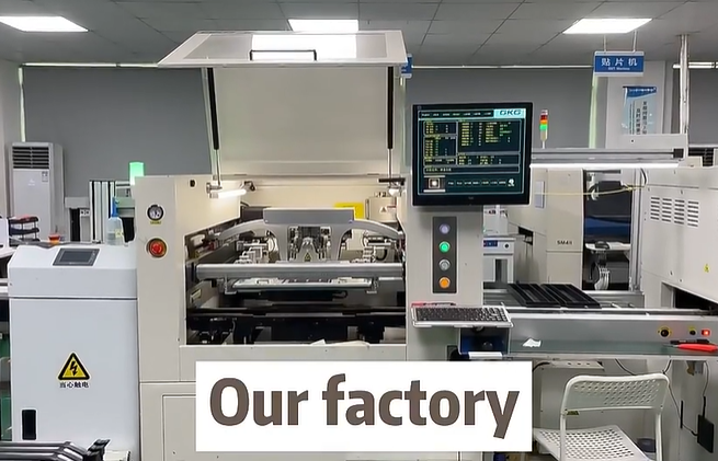
Fumax PCB manufacturing and testing factory is a factory specializing in PCB board production and testing. Our factory has advanced equipment and professional technical personnel, capable of producing high-quality PCB boards and conducting comprehensive testing on them.
The main work of the PCB manufacturing and testing factory includes the manufacturing and testing of PCB boards. Among them, the manufacturing process includes circuit board design, manufacturing and processing, while testing includes functional testing, performance testing, appearance inspection and other aspects. These tests are designed to ensure the quality and reliability of PCB boards to meet customer needs.
In PCB manufacturing and testing factories, various automation equipment and software are usually used for production and testing. For example, automatic optical inspection (AOI) equipment can automatically detect problems such as appearance defects and poor welding of PCB boards; in-circuit testing (ICT) equipment can quickly and effectively detect the connectivity and functionality of PCB boards. In addition, some factories will use flying probe testing equipment to test high-density PCB boards.
If you have PCB design, manufacturing, and PCB assembly services, please contact us.