Flexible circuit board manufacturing is a technology that transfers circuit designs to flexible materials and has the characteristics of high reliability, excellent electrical properties and excellent flexibility.
What is FPC flexible circuit board?
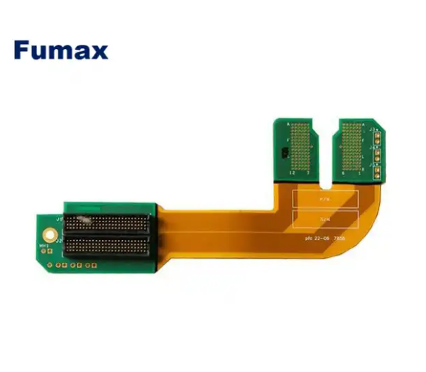
FPC flexible circuit board, also known as flexible printed circuit board or flexible circuit board, is a printed circuit board made of polyimide or polyester film. It has the characteristics of high wiring density, light weight, thin thickness, and good flexibility.
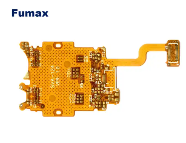
It can withstand millions of dynamic bends without damaging the wires. It can be moved and expanded at will to achieve the integration of component assembly and wire connection. .
FPC flexible circuit boards are widely used in high-tech electronic fields such as communications, computers, instruments, automobiles, medical care, industrial control, home appliances and CNC machine tools, camera modules, and intelligent battery management modules.
With the emergence of multi-functional modules for smartphones in the 5G era, FPC flexible circuit boards also play an important role in radio frequency modules, foldable screens, miniaturized models, etc.
FPC flexible circuit board manufacturing process and technology
The manufacturing process and technology of FPC flexible circuit boards are very complex. Let’s describe them in simple language. The main steps are as follows:
- Material preparation: The main materials of FPC flexible circuit boards include flexible substrates, conductive materials and insulating materials. These materials are usually supplied in roll form, and first need to be corrected or slitted by a slitting machine or slitting machine to accommodate the size requirements of various products.
- Pretreatment: FPC boards are relatively soft and are generally not vacuum packed when leaving the factory. They easily absorb moisture in the air during transportation and storage. They need to be pre-baked before SMT is put into the line to slowly and forcibly discharge the moisture. Otherwise, under the high-temperature impact of reflow soldering, the moisture absorbed by the FPC will quickly vaporize and turn into water vapor protruding out of the FPC, easily causing defects such as delamination and blistering of the FPC. The pre-baking conditions are generally a temperature of 80-100°C and a time of 4-8 hours. Under special circumstances, the temperature can be increased to above 125°C, but the baking time needs to be shortened accordingly. Before baking, be sure to conduct a small sample test to determine whether the FPC can withstand the set baking temperature. You can also consult the FPC manufacturer for suitable baking conditions. When baking, the FPCs should not be stacked too much. 10-20PNL is more suitable. Some FPC manufacturers will put a piece of paper between each PNL for isolation. You need to confirm whether the isolation paper can withstand the set baking. If the temperature cannot be reached, remove the isolation paper before baking. The baked FPC should have no obvious discoloration, deformation, warping and other defects, and must be inspected by IPQC before it can be put into production.
- Inner resist dry film: This step is to first make the circuit on the film, and then use an exposure machine to expose the circuit on the film on the substrate with the resist dry film (photosensitive film) attached, so that The wiring can be transferred to the copper foil.
- Acidic etching: When using chemical etching, it is easier to use acid such as hydrochloric acid or sulfuric acid for FPC soft boards, but when etching hard circuits, it is easy to use ammonia, etc. to show acidity.
- Chemical cleaning: This step is to prevent the residual solution from etching from being in the circuit, and then use plasma to clean the foreign matter on the FPC circuit board.
- Alignment of the inner covering film: Before this step, the appearance of the soft board covering film must first be shaped, and then the covering film and the FPC circuit board are aligned and initially fixed on the pads using a soldering iron.
- Pressing: Pressing is to fully combine the circuit board and the glue. The glue used between the copper foil and the covering film will flow and lay flat after being baked at high temperature, which will make the combination more complete.
- Baking: Baking conditions are generally 80-100°C and 4-8 hours. There should be no obvious discoloration, deformation, warping or other defects after baking.
- Printing characters on the FPC circuit board: It is also necessary to make the characters on the film onto the screen, and then use the screen to print the characters on the FPC circuit board.
In addition, the production process also includes steps such as solder mask coating, soldering, and finished product testing. Finally, quality inspection and defective product processing need to be carried out based on the test results.