Temperature sensor PCB schematic design and PCB assembly factory
Fumax provides services such as temperature sensor PCB schematic design and PCB assembly factory manufacturing.
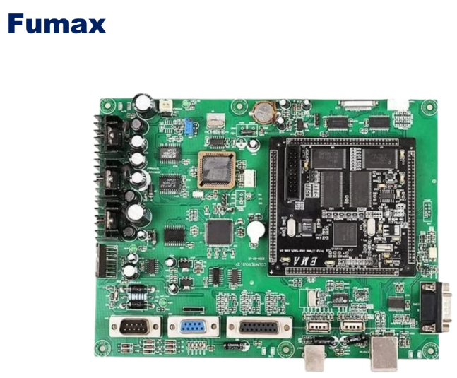
Fumax is a PCB manufacturing and PCB assembly company in China, providing professional PCB manufacturing, PCBA customization, PCB layout and other technical services to global customers.
- Temperature sensor PCB schematic design and PCB assembly factory
- Temperature sensor pcb schematic analysis
- Introduction to the design principles of temperature sensor PCB board
- Main steps of temperature display PCB board assembly process
- What are the precautions for temperature display PCB board assembly process?
- How does a temperature sensor work?
Temperature sensor PCB schematic design mainly involves circuit design, component layout, signal routing, electromagnetic compatibility design, and thermal design. During the design process, the corresponding circuit structure and component parameters need to be determined based on the specific type and measurement range of the temperature sensor. Factors such as the size, shape, number of layers, and dielectric materials of the PCB board also need to be considered.
In terms of PCB assembly factories, there are currently many PCB assembly factories at home and abroad. Some of the large PCB assembly factories have advanced production equipment and technical strength and can carry out high-precision and high-complexity PCB assembly production. At the same time, these factories usually have complete quality management systems and production planning management systems to ensure production quality and delivery time.
When choosing a PCB assembly factory, you need to consider factors such as the factory’s size, technical strength, quality management system, and delivery time. In addition, the factory’s equipment and processes also need to be inspected to ensure that they can meet production requirements.
In short, temperature sensor PCB schematic design and PCB assembly factory are important links in the temperature sensor manufacturing process. Through reasonable design and high-quality assembly production, high-performance and high-reliability temperature sensors can be produced to meet the needs of different fields.
Temperature sensor pcb schematic analysis
The analysis of the temperature sensor PCB schematic diagram requires an understanding of the working principle of the temperature sensor and the design principle of the PCB board.
How the temperature sensor works:
- Contact temperature sensor: This type of sensor device mainly uses temperature sensors made of thermal resistors and thermocouples. The basic principle is the thermoelectric effect. In contact temperature measurement, it is very important to unify the temperature standard (marking the temperature as 0°C as the benchmark). Usually a thermal resistor is used as the benchmark. The reference terminal temperature is required when measuring thermocouple temperature. The reference junction temperature must be constant. To ensure the accuracy of measurement.
- Basic principle of thermocouple temperature measurement: The basic principle of thermocouple temperature measurement is that two conductors of different compositions form a closed loop. When there is a temperature gradient at both ends, a current will pass through the loop. At this time, there will be a current flowing between the two ends. There is electromotive force – thermal electromotive force. From this principle, one advantage of thermocouples is that they do not require external power supply.
- Thermistor: Thermistor is a type of sensitive element. According to different temperature coefficients, it is divided into positive temperature coefficient thermistor (PTC) and negative temperature coefficient thermistor (NTC). The typical characteristic of a thermistor is that it is sensitive to temperature and exhibits different resistance values at different temperatures. The material of the thermistor is a semiconductor material, and its working principle is the Seebeck effect and the Piltz effect.
- Integrated temperature sensor: The integrated temperature sensor is a special IC that integrates the temperature sensor on a chip and can complete the functions of temperature measurement and signal output. Integrated temperature sensors often use operational amplifier gain and comparator units to form a digital temperature sensor.
Introduction to the design principles of temperature sensor PCB board
Design principle of temperature sensor PCB board:
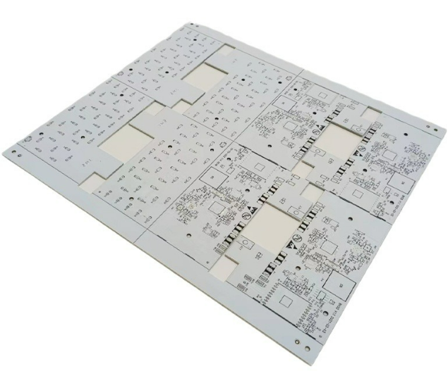
- Component layout: Place components in a certain order according to circuit functional requirements.
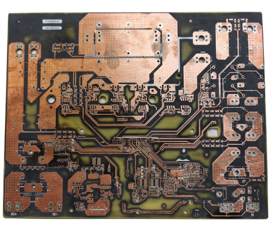
- Wiring design: According to the circuit functional requirements, the wiring design is carried out according to the space, current requirements and signal characteristics of the PCB board.
- Electromagnetic compatibility design: Considering electromagnetic compatibility issues, it is necessary to avoid mutual interference between signal lines when designing wiring, and also to avoid interference between signal lines and power lines or ground wires.
- Thermal design: Consider the heat generation and heat dissipation methods of components, and rationally arrange the location and wiring direction of components for better heat dissipation design.
When analyzing the temperature sensor PCB schematic diagram, it is necessary to analyze based on the above principles to understand the role and relationship of each component in the circuit, so as to better understand the working principle of the entire circuit.
Main steps of temperature display PCB board assembly process
The temperature display PCB board assembly process mainly includes the following steps:
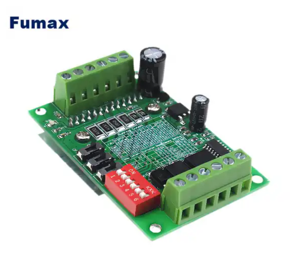
- Place components: First, place components that closely match the structure, such as power sockets, indicator lights, switches, connectors, interfaces, etc. Secondly, place special components, such as large components, heavy components, heating components, IC, etc. Finally, place the small components. Routing should be considered when laying out components, and try to choose a layout design that is conducive to routing. The crystal oscillator should be placed close to the IC. The layout of the IC decoupling capacitor should be as close as possible to the power pin of the IC, and the shortest loop between it and the power supply and ground should be kept. Heating components should generally be evenly distributed to facilitate heat dissipation of the single board and the entire machine. Temperature-sensitive components other than temperature detection components should be kept away from components that generate large amounts of heat.
- Keep high-speed signal traces as short as possible and key signal traces as short as possible. Don’t drill too many via holes for one trace, no more than two via holes. The wiring corners should be larger than 90 degrees as much as possible, avoid corners below 90 degrees, and use 90-degree corners as little as possible.
What are the precautions for temperature display PCB board assembly process?
Precautions for the temperature display PCB board assembly process include:
- Design specifications: Follow the design specifications for circuit design to ensure that the circuit performance meets the requirements.
- Component selection: Select components that meet the requirements and pay attention to quality and reliability.
- Restricted production: According to the needs of PCB processing technology, restricted production factors such as line buffer, pad size, and solder mask spacing are rationally utilized.
- Pin connection: Pay attention to components with a large number of pins, and the connection method should be reasonable to avoid the Saturn effect and signal crosstalk.
- Design layout: Arrange circuit components reasonably to minimize line length and improve signal transmission effect.
- Keep the pins and silk screen aligned: to facilitate subsequent assembly and repair.
How does a temperature sensor work?
The working principles of temperature sensors mainly include the following:
- Contact temperature sensor: This type of sensor device mainly uses temperature sensors made of thermal resistors and thermocouples. The basic principle is the thermoelectric effect. In contact temperature measurement, it is very important to unify the temperature standard (marking the temperature as 0°C as the benchmark). Usually a thermal resistor is used as the benchmark. The reference terminal temperature is required when measuring thermocouple temperature. The reference junction temperature must be constant. To ensure the accuracy of measurement.
- Basic principle of thermocouple temperature measurement: The basic principle of thermocouple temperature measurement is that two conductors of different compositions form a closed loop. When there is a temperature gradient at both ends, a current will pass through the loop. At this time, there will be a current flowing between the two ends. There is electromotive force – thermal electromotive force. From this principle, one advantage of thermocouples is that they do not require external power supply.
- Thermistor: Thermistor is a type of sensitive element. According to different temperature coefficients, it is divided into positive temperature coefficient thermistor (PTC) and negative temperature coefficient thermistor (NTC). The typical characteristic of a thermistor is that it is sensitive to temperature and exhibits different resistance values at different temperatures. The material of the thermistor is a semiconductor material, and its working principle is the Seebeck effect and the Piltz effect.
- Integrated temperature sensor: The integrated temperature sensor is a special IC that integrates the temperature sensor on a chip and can complete the functions of temperature measurement and signal output. Integrated temperature sensors often use operational amplifier gain and comparator units to form a digital temperature sensor.
To learn more about temperature sensor PCB assembly and pcb manufacturing knowledge, please follow us. fumax provides you with comprehensive technical services.