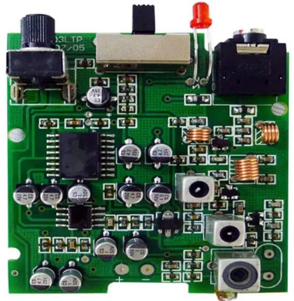
The digital thermometer PCB structure is a single panel, using a single-chip microcomputer as the controller, adding a temperature display module and a power module. The PCB structure can also be customized according to user needs.
- PCB design and assembly production process of digital display thermometer
- What should you pay attention to when designing and making PCB for digital display thermometer?
- What are the steps in the PCB design and production process of a digital display thermometer?
- What components are selected in the design of a thermometer circuit?
- Introduction of the best digital display thermometer PCB design and assembly manufacturer in China
PCB design and assembly production process of digital display thermometer
The PCB design and production process of the digital display thermometer is described in detail as follows:
- Requirements analysis
Before making a PCB for a digital display thermometer, you first need to clarify the needs and functions of the product. Digital display thermometers usually need to measure temperature and display it, and may need to have other additional functions, such as high temperature alarm, low temperature alarm, temperature recording, etc. Based on the demand analysis, a preliminary plan for PCB design can be determined.
- Circuit design
- Component selection: Based on demand analysis, select appropriate temperature sensors, microcontrollers, display modules and other necessary components. The temperature sensor can be a common thermistor or semiconductor sensor; the microcontroller can be a common microcontroller or embedded controller; the display module can be an LED digital tube, LCD screen or OLED display.
- Circuit schematic design: Use circuit design software to design a circuit schematic diagram based on component parameters and connection relationships. In the schematic diagram, the model, specification and connection relationship of each component need to be marked, and the correct connection of the power supply and ground wires must be ensured.
- PCB layout design: According to the circuit schematic diagram, reasonably lay out each component on the PCB board. When laying out, factors such as the order of components, simplicity of wiring, and maintainability need to be considered. At the same time, attention should be paid to the handling of power supply and ground wires to ensure that the design of the power supply and ground wire network is reasonable and reliable.
- PCB wiring design: Use PCB design software for wiring according to the circuit schematic and layout design. PCB design rules need to be followed when wiring to ensure appropriate selection of signal line width, spacing and number of layers to avoid problems such as signal interference and short circuits.
- PCB manufacturing
- Prepare materials: According to the designed PCB drawings, prepare materials such as copper clad laminate, copper foil, solder, and electronic components.
- Make welding pads: Make welding pads on the copper-clad board according to the PCB design drawings. The production of pads requires the use of a drilling machine to drill holes, and then electroplating or chemical plating to deposit a metal layer in the holes.
- Mount components: Place the electronic components on the pads according to the position and direction on the PCB drawing. When mounting, you need to pay attention to the polarity and direction of the components to avoid errors.
- Soldering: Use solder to solder components and pads together to form a complete circuit. When welding, you need to pay attention to temperature and time to ensure welding quality and component safety.
- Testing: After completing the welding, perform functional testing and performance testing on the PCB to ensure that the quality and performance of the product meet the requirements.
- PCB board inspection and correction
After the production is completed, the PCB board needs to be inspected and corrected. Inspection includes visual inspection and functional inspection. Visual inspection mainly checks whether the appearance of the PCB board is smooth, whether the components are arranged neatly, whether the solder joints are full, etc.; functional inspection mainly tests whether the various functions of the product are implemented normally. If a problem is detected, corrections need to be made, such as re-soldering, component replacement, etc.
- Summary
The PCB design and production process of digital display thermometer includes requirements analysis, circuit design, PCB manufacturing, detection and correction, etc. In circuit design, it is necessary to select appropriate components according to product requirements, design reasonable circuit schematics and PCB layout; in PCB manufacturing, it is necessary to prepare materials, make pads, mount components, weld and test and other steps; in detection and correction Visual inspection and functional inspection are required, and problems must be corrected. Use these steps to create a high-quality digital display thermometer PCB board.
What should you pay attention to when designing and making PCB for digital display thermometer?
The following points need to be noted in the PCB design and production of digital display thermometers:
- Component selection: Select the appropriate temperature sensor, microcontroller, display module and other necessary components, pay attention to the component model, specifications and connection relationship, and ensure the correct connection of the power supply and ground wire.
- Layout design: Reasonably lay out each component on the PCB board, taking into account factors such as the order of components, simplicity of wiring, and maintainability. At the same time, attention should be paid to the handling of power supply and ground wires to ensure that the power supply and ground wire network The design is reasonable and reliable.
- Wiring design: According to the circuit schematic and layout design, use PCB design software for wiring, follow PCB design rules, and ensure the appropriate selection of signal line width, spacing, and number of layers to avoid problems such as signal interference and short circuits.
- Consider scalability: When designing PCB, possible future needs and expansions should be considered, such as adding more sensors, adding more functions, etc.
- Testing and verification: After completing the PCB design, functional testing and performance testing are required to ensure that the quality and performance of the product meet the requirements. If there is a problem, it needs to be corrected, such as re-soldering, replacing components, etc.
- Documentation: During the PCB design and production process, detailed documentation should be recorded, including design drawings, material lists, test reports, etc., to facilitate subsequent maintenance and upgrades.
- Comply with safety regulations: When designing and producing PCBs, you should comply with relevant safety regulations and standards to ensure the safety and reliability of the product.
In short, the PCB design and production of digital display thermometers requires attention to component selection, layout design, wiring design, scalability, testing and verification, documentation and compliance with safety regulations. Only by comprehensively considering these factors can a high-quality digital display thermometer PCB board be produced.
What are the steps in the PCB design and production process of a digital display thermometer?
The PCB design and production process of a digital display thermometer includes the following steps:
- Determine requirements and functions: Clarify the requirements and functions of the product, including measurement range, accuracy, display method, etc.
- Select the appropriate components: Select the appropriate temperature sensor, microcontroller, display module and other necessary components according to your needs.
- Design the circuit schematic diagram: Use circuit design software to design the circuit schematic diagram based on component parameters and connection relationships.
- Design PCB layout: According to the circuit schematic diagram, reasonably lay out each component on the PCB board. Consider factors such as the order of components, simplicity of wiring, and maintainability.
- Design PCB wiring: According to the circuit schematic and layout design, use PCB design software for wiring. Follow PCB design rules to ensure appropriate selection of signal line width, spacing and number of layers to avoid problems such as signal interference and short circuits.
- Make welding pads: Make welding pads on the copper-clad board according to the PCB design drawings. The production of pads requires the use of a drilling machine to drill holes, and then electroplating or chemical plating to deposit a metal layer in the holes.
- Place components: Place the electronic components on the pads according to the position and direction on the PCB drawing. When mounting, you need to pay attention to the polarity and direction of the components to avoid errors.
- Soldering: Use solder to solder components and pads together to form a complete circuit. When welding, you need to pay attention to temperature and time to ensure welding quality and component safety.
- Testing: After completing the welding, perform functional testing and performance testing on the PCB to ensure that the quality and performance of the product meet the requirements.
- Correction and optimization: If problems are detected, corrections need to be made, such as re-soldering, replacing components, etc. At the same time, the PCB can be optimized to improve product performance and reliability.
- Documentation: During the PCB design and production process, detailed documentation should be recorded, including design drawings, material lists, test reports, etc., to facilitate subsequent maintenance and upgrades.
The above are the general steps of the PCB design and production process of a digital display thermometer. The specific steps may vary depending on product requirements and actual conditions.
What components are selected in the design of a thermometer circuit?
In the thermometer circuit design, the components selected include:
- Temperature sensor: used to sense temperature and convert it into an electrical signal. Common temperature sensors include thermistors, semiconductor sensors, etc.
- Microcontroller: used to process sensor signals and control the display module. Common microcontrollers include microcontrollers, embedded controllers, etc.
- Display module: used to display the measured temperature value. Common display modules include LED digital tubes, LCD screens, OLED displays, etc.
- Power supply and power management devices: used to provide stable power supply, such as voltage regulators, capacitors, etc.
- Interface device: used to connect microcontrollers and other devices, such as RS-232 interface, I2C interface, etc.
- Protection devices: used to protect circuits from overvoltage, overcurrent, etc., such as fuses, varistors, etc.
- Other auxiliary devices: such as resistors, capacitors, diodes, etc.
Depending on the specific application needs and circuit design requirements, appropriate component models and specifications can be selected. At the same time, the layout and wiring of components also need to be considered in circuit design to ensure the stability and reliability of the circuit.
Introduction of the best digital display thermometer PCB design and assembly manufacturer in China
Shenzhen fumax Technology Co., Ltd. is a PCB and PCBA manufacturer headquartered in Shenzhen, China, established in 2007. Is one of the world’s leading PCB and PCBA manufacturers.
Shenzhen fumax Technology Co., Ltd. provides high-quality PCB solutions for various electronic products. It is one of the world’s flexible printed circuit board suppliers.
A large PCB manufacturer in China, engaged in temperature and humidity sensor control board PCBA design, PCB assembly customization, and prototype PCB processing factory.
Focus on PCB circuit board manufacturing manufacturers, which can produce single/double-sided PCB circuit boards, 2-28 layer multi-layer PCB boards, aluminum substrates, high TG thick copper boards, soft-hard board, high-frequency PCB boards, mixed media laminates, Blind and buried via circuits, professional OEM/ODM factory, from customer needs, material procurement, program development.