Shenzhen Fumax Technology Co., Ltd. is a PCBA customization factory in China. The company provides one-stop services such as prototype PCB customization, PCBA design and testing.
Fumax is a professional PCB OEM factory water pump controller hardware system design expert with many years of experience in PCB assembly and PCB electronic design. Let’s take a look at some knowledge about the hardware system design of water pump controller in PCB OEM factory.
- PCB OEM factory water pump controller hardware system design
- What is water pump controller module PCB design?
- What does the water pump controller circuit board mainly consist of?
- Key steps in PCB OEM factory water pump controller hardware system design
- Can you provide a complete electronic water pump controller design list?
- What are the main functions of an electronic water pump controller?
- What tests do PCB assembly manufacturers mainly perform on the function of water pump control system modules?
- What are the water pump control module PCB design and manufacturing factories in China?
- What are the steps involved in water pump controller module PCB design?
- What factors should be paid attention to when designing the PCB of the water pump controller module?
- How to reduce costs by cooperating with Chinese PCB assembly manufacturers?
PCB OEM factory water pump controller hardware system design
What is water pump controller module PCB design?
Water pump controller module PCB design refers to the design process of the water pump controller circuit board, including circuit board layout, wiring and component selection. The purpose is to integrate various components and circuit boards of the water pump controller to realize various functions of the water pump controller and ensure its stability and reliability.
In the water pump controller PCB design, the following factors need to be considered:
- Circuit board size and shape: Determine the size and shape of the circuit board based on the needs and space constraints of the water pump controller.
- Selection of components: According to the functional requirements of the water pump controller, select appropriate electronic components and devices, such as microcontrollers, power modules, sensors, etc.
- Circuit board layout: Reasonably arrange the positions of various components on the circuit board to achieve the best layout of the circuit board.
- Circuit board wiring: According to the circuit schematic diagram and design rules, connect various components to form a complete circuit.
- Welding and fixing of components: Choose appropriate welding methods and materials to ensure that each component is welded firmly and beautifully. At the same time, consider the fixing method of the circuit board to ensure its stability and reliability.
- Testing and maintenance: After completing the PCB design, corresponding testing and maintenance work is required to ensure the quality and reliability of the circuit board.
In short, the PCB design of the water pump controller module is one of the important links in realizing the function of the water pump controller. Many factors need to be considered to ensure the rationality and reliability of the design.
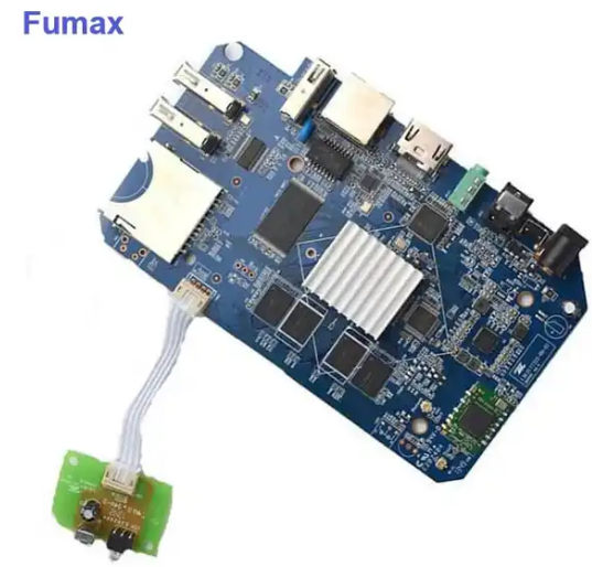
What does the water pump controller circuit board mainly consist of?
The water pump controller circuit board mainly consists of the following parts:
- Microcontroller: As the core component, the microcontroller is responsible for receiving input signals, processing data and controlling the operation of the water pump.
- Power circuit: Provides stable and reliable power for the entire controller, usually including power input, power conversion and filtering.
- Input signal acquisition circuit: used to receive input signals such as water level sensors and convert them into electrical signals that can be processed by the microcontroller.
- Control circuit: Controls the operating status of the water pump according to the instructions and input signals of the microcontroller.
- Driving circuit: drives the switch state of the water pump according to the instructions of the microcontroller.
- Communication circuit: used to communicate with the host computer to achieve remote control and data transmission.
- Other auxiliary circuits: such as protection circuits, indication circuits, etc., used to protect and control the operation of the water pump.
In addition, the water pump controller circuit board also includes components such as connecting cables, fasteners and insulation materials to ensure the connection and fixation between the circuit board and various components.
The water pump control bit module is mainly composed of microprocessor, relay, sensor and communication interface. Among them, the microprocessor is the core component, which receives input signals, processes data and controls the operation of the water pump. The relay is used to control the on/off status of the water pump according to the instructions of the microprocessor, the sensor is used to detect input signals such as water level status, and the communication interface is used to communicate with the host computer to achieve remote control and data transmission. In addition, the water pump control bit module also includes auxiliary circuits such as power circuits and protection circuits to ensure the connection and fixation between the circuit board and various components.
Key steps in PCB OEM factory water pump controller hardware system design
The electronic water pump controller hardware system design includes the following main parts:
- Power circuit: The power circuit is responsible for converting the input power into the stable voltage required by the controller. It needs to include a power switch, a power indicator light, a power filter and other components.
- Signal acquisition circuit: The signal acquisition circuit is responsible for acquiring signals from equipment such as water level sensors and converting these signals into electrical signals that the controller can process.
- Control circuit: The control circuit is the core of the water pump controller. It determines the current water level status based on the signal obtained by the signal acquisition circuit, and then controls the operating status of the water pump according to the set rules.
- Drive circuit: The drive circuit is responsible for controlling the on/off state of the water pump according to the instructions of the control circuit.
- Communication circuit: The communication circuit is responsible for communicating between the controller and the host computer so that the user can remotely control the status of the water pump.
During the design process, factors such as power supply stability, signal anti-interference, and controller durability need to be taken into consideration. At the same time, control rules need to be set according to actual needs, such as controlling the on/off status of the water pump according to the level of the water level.
Can you provide a complete electronic water pump controller design list?
Below is a complete electronic water pump controller design checklist including the main components and their functions:
1. Power circuit:
- Power switch: used to control the power on and off;
- Power indicator light: displays power status;
- Power supply filter: Reduce noise interference in the power supply.
2. Signal acquisition circuit:
- Water level sensor: detects water level status;
- Signal amplifier: Amplify the signal of the water level sensor;
- A/D converter: Converts analog signals into digital signals for processing by the controller.
3. Control circuit:
- MCU (microcontroller): executes the control algorithm and controls the operation of the water pump according to the water level status;
- Memory: stores control programs and setting parameters;
- Input and output interface: interact with users, such as displaying water level status, water pump operating status, etc.
4. Drive circuit:
- Relay or solid-state relay: control the switch state of the water pump according to the instructions of the MCU;
- Protection circuit: such as over-current protection, over-voltage protection, etc., to ensure the safe operation of the water pump.
5. Communication circuit:
- RS485 and other communication interfaces: realize communication with the host computer and perform remote control;
- Communication protocol converter: Convert internal data into a format that complies with communication interface specifications.
6. Other components:
- Connection cables: used to connect various circuit boards and external devices;
- Fasteners and insulation materials: used to secure and protect circuit boards and cables.
It should be noted that the above is only an example design list, and the actual design may need to be adjusted and optimized according to specific needs. At the same time, electronic and electrical designs must also comply with relevant safety regulations and standards.
What are the main functions of an electronic water pump controller?
The main function of the electronic water pump controller is to realize automatic control and protection of the water pump. Specifically, it can automatically detect and adjust based on water level, pressure and other parameters, effectively reducing the operator’s work intensity.
At the same time, it can also protect the water pump from damage due to abnormal operating conditions such as overflow, underflow, overvoltage, and undervoltage, and extend the service life of the water pump.
In addition, the electronic water pump controller also has remote communication functions, which facilitates remote monitoring and control by users. In short, the main function of the electronic water pump controller is to realize automatic control and protection of the water pump, improve work efficiency and equipment reliability.
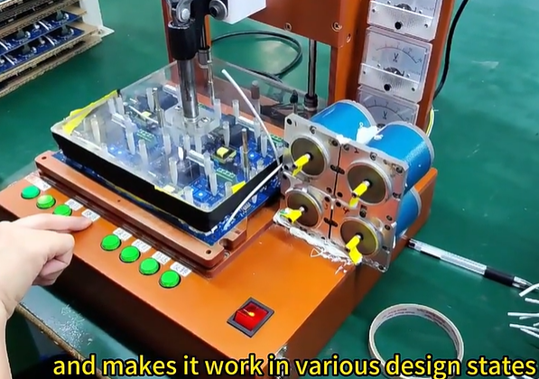
What tests do PCB assembly manufacturers mainly perform on the function of water pump control system modules?
For water pump PCB assembly manufacturers, functional testing of water pump control system modules mainly includes the following aspects:
- Power supply test: Check whether the power circuit is working normally, including whether the voltage and current of the power supply are within the normal range.
- Signal acquisition test: Verify whether the water level sensor and other input signals are correctly transmitted to the control board, and check the quality and stability of the signals at the same time.
- Control function test: Verify whether the control logic and algorithm of the water pump controller are correct. This includes whether the water pump can automatically turn on and off under different water level conditions, and whether it can achieve other preset functions.
- Drive test: Check whether the drive circuit can drive the water pump correctly, including performance during opening and closing processes.
- Communication function test: Verify whether the communication between the water pump controller and the host computer is normal, including the correctness of the communication interface, protocol and data transmission.
- Protection function test: Verify whether the water pump controller has over-current, over-voltage and other protection functions to ensure that the water pump can be automatically protected from damage under abnormal circumstances.
- Appearance and structure test: Check whether the appearance and structure of the water pump controller meet the design requirements, and whether the connection parts are firm and waterproof.
- Environmental adaptability test: Verify the performance of the water pump controller under different environmental conditions, such as temperature, humidity, pressure, etc.
These tests are to ensure that the water pump control system modules are functioning properly, stably, and meeting design requirements. Through these tests, potential problems and failures can be discovered and corrected, thereby improving product quality and reliability.
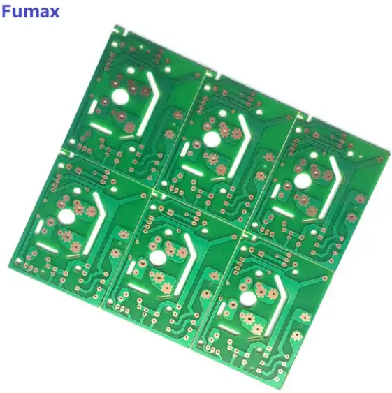
What are the water pump control module PCB design and manufacturing factories in China?
The following are Chinese water pump controller module manufacturers provided by fumax. These manufacturers specialize in PCB design and production, LED PCB manufacturing, air pump circuit board assembly, and vehicle pump hardware chip module PCBA design.
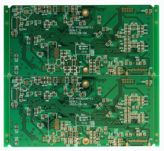
What are the steps involved in water pump controller module PCB design?
The water pump controller module PCB design includes the following steps:
- Determine design requirements and specifications: clarify the function and performance requirements of the water pump controller, understand relevant standards and specifications, and provide guidance and basis for design.
- Determine the design plan: According to the design requirements and specifications, select the appropriate circuit board layout and components and formulate the design plan.
- Draw the circuit schematic diagram: Use circuit design software to draw the circuit schematic diagram and connect the various components to form a complete circuit.
- Component selection and confirmation: According to the circuit schematic diagram, select appropriate electronic components and devices to ensure that their parameters and specifications meet the design requirements.
- Circuit board layout design: According to the design plan, place each component on the circuit board in a reasonable position to ensure that the circuit board layout is reasonable and beautiful.
- Circuit board wiring design: According to the circuit schematic and layout design, connect the pins of each component with wires to form a complete circuit.
- Circuit board manufacturing file generation: Convert circuit board layout and wiring design results into manufacturing files, including light drawing files, drilling files, etc., for circuit board production.
- Circuit board production: According to the manufacturing documents, make the circuit board and complete the corresponding welding and debugging work.
- Testing and verification: Carry out functional testing and verification on the produced circuit board to ensure that it meets the design requirements and performance standards.
- Optimization and improvement: Based on the test and verification results, the circuit board is optimized and improved to improve product performance and reliability.
The above are the general steps for water pump controller module PCB design. The specific design process may vary depending on actual needs and project requirements.
What factors should be paid attention to when designing the PCB of the water pump controller module?
The water pump controller module PCB design needs to pay attention to the following factors:
- Size and layout: Layout according to the size requirements of the product, and reasonably arrange the position and size of each component to make full use of the space and ensure smooth access to the lines. At the same time, lines should be kept short and concise to reduce signal interference and power consumption.
- Power supply and ground wire: Power supply and ground wire are the two most important components in PCB design. The power cord should be as short as possible and avoid crossing or running in parallel with other signal lines to reduce electromagnetic interference. Ground wires should be run parallel to power wires to enhance signal loop performance.
- Component selection: According to the design requirements and specifications, select appropriate electronic components and devices to ensure that their parameters and specifications meet the design requirements. At the same time, the reliability and durability of components should be considered to avoid failure of the entire controller due to component failure.
- Circuit board wiring: According to the circuit schematic and layout design, connect the pins of each component with wires to form a complete circuit. The wiring should be concise and clear, follow the design rules, and avoid cross, parallel, right angle, etc. situations that may cause signal interference or short circuit.
- Component welding and fixing: Choose appropriate welding methods and materials to ensure that each component is welded firmly and beautifully. At the same time, consider the fixing method of the circuit board to ensure its stability and reliability.
- Testing and maintenance: After completing the PCB design, corresponding testing and maintenance work is required to ensure the quality and reliability of the circuit board. Testing should include functional testing, performance testing, environmental adaptability testing and other aspects to ensure that the controller can operate normally under various conditions.
- Safety considerations: Safety issues should be considered in the design, such as preventing damage to the water pump and circuit board due to overcurrent, overvoltage and other abnormal conditions. Corresponding protection circuits and measures can be set up to ensure the safe operation of the water pump and circuit board.
- Appearance and structure: Consider the appearance and structure of the circuit board to coordinate with the overall structure of the water pump controller. At the same time, the maintainability and repairability of the circuit board should be considered to facilitate future maintenance and upgrades.
- Cost consideration: On the premise of meeting design requirements, the cost of PCB design should be reduced as much as possible, such as selecting appropriate components and materials, optimizing circuit design, etc., to improve the market competitiveness of the product.
The above are some factors that need to be paid attention to when designing the water pump controller module PCB. These factors need to be carefully considered and weighed during the entire design process to ensure the rationality and reliability of the design.
How to reduce costs by cooperating with Chinese PCB assembly manufacturers?
There are many ways to reduce costs by working with Chinese PCB assembly manufacturers. Here are some suggestions:
- Optimize design: Use CAD software programs to design PCBs and ensure that the designs comply with industrial standards such as electromagnetic compatibility (EMC). By optimizing layout and routing, the number of connecting wires and contacts can be reduced, thereby reducing manufacturing costs.
- Choose the appropriate manufacturing process: Choose the appropriate PCB manufacturing process according to actual needs, such as multi-layer boards, high-density connectors, etc. These processes can provide better electrical performance and smaller size, thus reducing costs.
- Consider using packaged chips: Packaged chips can package multiple chips together, reducing the space required to connect the chips on the PCB and reducing manufacturing costs. At the same time, it can improve the stability and durability of the equipment and reduce the number of maintenance times.
- Bulk purchasing: Negotiate bulk purchasing agreements with PCB assembly manufacturers to obtain better prices. In addition, long-term cooperation can be considered to obtain more stable supply and lower prices.
- Optimize supply chain management: By optimizing supply chain management, inventory and transportation costs can be reduced. At the same time, long-term cooperative relationships can be established with suppliers to ensure stable supply of raw materials and stable prices.
- Consider using automated production lines: Production efficiency can be improved and labor costs reduced by using automated production lines. At the same time, product quality and consistency can be improved, and the defective product rate and return rate can be reduced.
- Regular audits and evaluations: Regularly audit and evaluate PCB assembly manufacturers to ensure that they meet quality standards and delivery requirements. Costs can be reduced by reducing quality issues and delivery delays.
- Training and management: Improve employee skills and efficiency and reduce labor costs through training and management. At the same time, it can establish a good corporate culture and improve employees’ work enthusiasm and production efficiency.
- R&D and innovation: Improve the competitiveness and added value of products through R&D and innovation. By continuously improving design and manufacturing processes, costs can be reduced and market competitiveness improved.
In short, cooperating with Chinese PCB assembly manufacturers to reduce costs requires starting from many aspects, including optimizing design, selecting appropriate manufacturing processes, bulk purchasing, optimizing supply chain management, adopting automated production lines, regular audits and evaluations, training and management, and R&D and innovation, etc.