With the continuous development of LED technology and the expansion of application fields, LED lighting products are increasingly used in various fields. LED PCB design is a key link in the manufacturing of LED lighting products, and its importance is self-evident.
When designing LED PCB, you need to use some professional software tools. Here are some commonly used LED PCB design software.
Top 5 software needed for LED PCB design
AutoCAD
AutoCAD is a widely used CAD software that provides comprehensive drawing and design tools for LED PCB design.
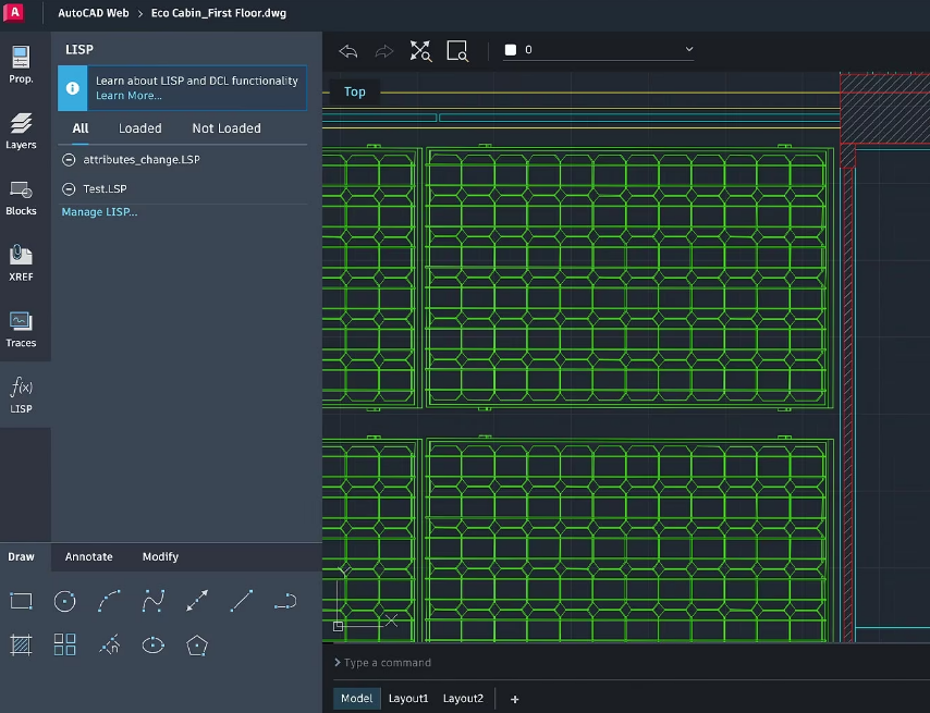
This software has powerful functions and flexibility and can be used to draw PCBs for various types of LED lighting products. When using AutoCAD for LED PCB design, you can easily create circuit board diagrams, component layouts, wiring diagrams, etc., and you can also perform PCB board simulation and analysis.
Eagle
Eagle is a professional PCB design software widely used in the electronics and LED lighting industries. The software offers ease of use and flexibility to quickly create and edit PCB designs for LED lighting products.
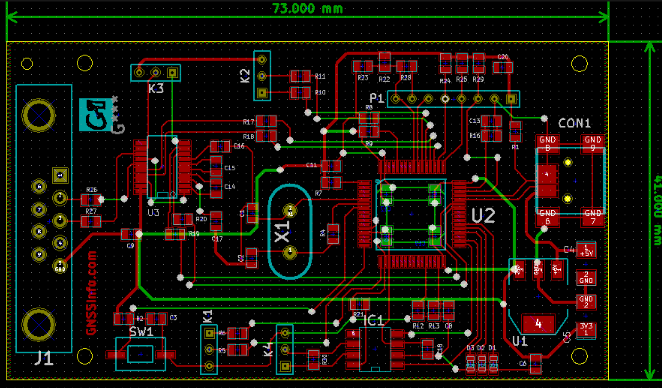
Eagle provides a rich component library, wiring tools and layout tools to help designers quickly realize automated design and wiring of PCB boards. In addition, the software provides powerful simulation and analysis tools that can be used to verify PCB performance and reliability.
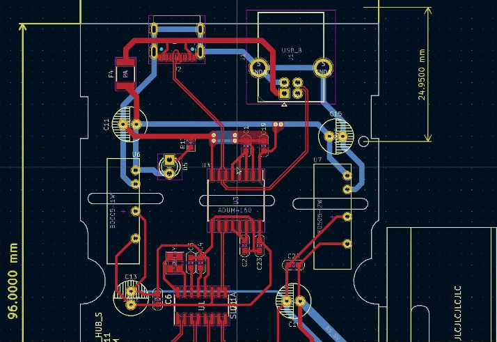
KiCad
KiCad is an open source PCB design software with a wide range of functions and adaptability that can be used for PCB design of LED lighting products. The software supports many different board types and component libraries, making circuit analysis and simulation easy. KiCad’s interface is simple, intuitive, and easy to use. It also provides powerful layout and wiring tools that can help designers quickly realize automated design and wiring of PCB boards.
Altium Designer
Altium Designer is a professional PCB design and EDA software that can be used for PCB design of LED lighting products. The software has comprehensive circuit board design, component placement, routing and testing functions to help designers quickly achieve high-quality PCB designs.
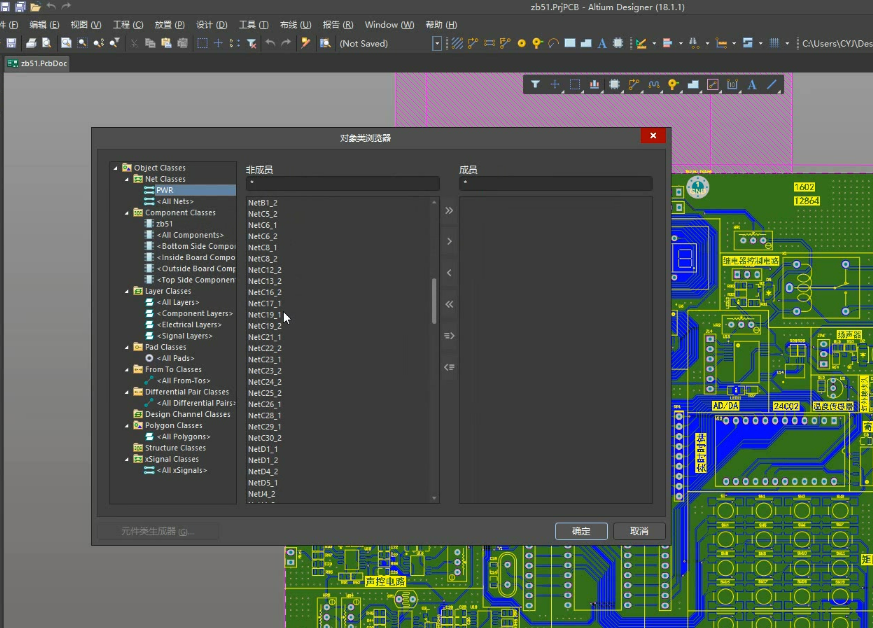
Altium Designer supports a variety of different circuit board types and component libraries, while providing powerful simulation and analysis tools that can be used to verify PCB performance and reliability.
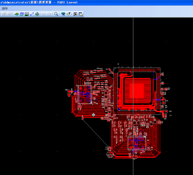
PADS
PADS is a professional PCB design software widely used in the electronics and LED lighting industries. The software offers ease of use and flexibility to quickly create and edit PCB designs for LED lighting products. PADS provides a rich component library, wiring tools and layout tools, which can help designers quickly realize automated design and wiring of PCB boards. In addition, the software provides powerful simulation and analysis tools that can be used to verify PCB performance and reliability.
In short, when designing LED PCB, you need to use professional software tools to achieve efficient and accurate design. Several LED PCB design software introduced above have different characteristics and advantages. Designers can choose the software tools that suit them according to actual needs. At the same time, with the continuous development and advancement of technology, I believe that more excellent LED PCB design software tools will appear in the future.
Fumax PCB Design Company
The services provided by PCB design companies include: PCB board design, circuit board layout, component packaging design, BOM table production, Gerber file generation, CAM file output, etc. In addition, some PCB design companies also provide services such as project management, technical support, after-sales service, and customized solutions.
These services are designed to help customers simplify the PCB design process, improve production efficiency, reduce costs, and ensure product quality and reliability.
PCB LED design software FAQs and answers
AutoCAD is a computer-aided design software. It was first developed by Autodesk in 1982. It is an automatic computer-aided design software mainly used for two-dimensional drawing, detailed drawing, design documents and basic three-dimensional design. It has now become an internationally widely used software. Popular drawing tool.
Different versions of AutoCAD have their own features and advantages. Which version is easier to use mainly depends on the user’s specific needs and usage scenarios.
Some popular versions include AutoCAD 2007, AutoCAD 2014, AutoCAD 2020, etc. These versions have excellent performance in terms of functionality, stability and compatibility, and are widely used in various industries and fields. In addition, other AutoCAD versions such as AutoCAD 2010, AutoCAD 2016, AutoCAD 2018 and AutoCAD 2023 are also favored by users.
In general, which version of AutoCAD to choose mainly depends on the user’s specific needs and usage scenarios. It is recommended to choose the appropriate version based on the actual needs of individuals or businesses.
Eagle PCB design software can be downloaded from its official website. You need to visit Eagle’s official website, then find the download page, and select the version suitable for your operating system to download. After the download is complete, you need to unzip the installation package and run the installation program, and follow the prompts, including selecting the installation path, accepting the agreement, etc. Once the installation is complete, you can start using Eagle for circuit design.
KiCad is a free, open source electronic design automation (EDA) software for creating circuit schematics and printed circuit board (PCB) designs. It has an integrated development environment that includes multiple independent software tools, such as circuit schematic editor, PCB layout and routing tools, library management, etc. KiCad supports a variety of file formats, including Gerber, Excellon, IPC-D-356a, etc., and can interact with other EDA software for data.
Cross-platform: Can run on operating systems such as Windows, Linux and Mac OS X.
Highly customizable: KiCad provides a wealth of plug-ins and extension mechanisms that users can customize according to their own needs.
Rich libraries: KiCad comes with a large number of component libraries, and more component libraries can also be downloaded through the Internet.
Powerful PCB design function: KiCad’s PCB design tool supports a variety of board layers and constraints, can perform automatic routing and manual routing, and supports electrical connections and signal integrity analysis between components.
Community support: KiCad has an active community where users can get help, exchange experiences and learn skills.
KiCad is a powerful, easy-to-use, highly customizable free and open source EDA software suitable for electronic design engineers, embedded system developers, hardware designers and other fields.
The steps to add a component library in Altium Designer are as follows:
Start the Altium Designer software and select the “Library” option on the right.
In the pop-up interface, select the “Libraries” option in the upper left corner.
After selecting, a window will pop up, select the “Installed”-“Install” option.
Once selected, select Add library from file.
Select the file type, which can be modified to all types of files, and find the component library that needs to be added.
After clicking Finish, the device library is successfully added.
It should be noted that Altium Designer supports many types of component libraries, and you need to select the appropriate component library to add based on actual needs. At the same time, when adding a component library, you also need to pay attention to the compatibility and version issues of the component library.
In PADS design, DFF (Design Rule Checking) refers to design rule checking, which is used to verify whether the PCB design complies with a series of preset rules. These rules cover various aspects such as physical design, electrical performance, manufacturability, etc.
During DFF inspection, PADS will conduct a comprehensive inspection of the PCB design according to preset rules. If any issues are found that do not comply with the rules, PADS generates an error report that includes details of the issue and where it occurred.
When dealing with DFF errors, it is recommended to first carefully read the error report to understand the nature of the problem and where it occurred. Then, based on the information in the error report, make corresponding corrections to the PCB design. If you encounter a special DFF error or manufacturing issue, you should communicate with the PCB manufacturer promptly, as the manufacturer can usually provide suggestions or guidance on how to solve the problem.