The detailed list of components required for motor controller PCB board assembly includes microprocessors, power circuits, power devices, sensors, interface circuits, protection circuits, buttons and displays, resistors, capacitors, diodes, crystal oscillators, etc.
- Detailed list and functions of components required for motor controller PCB board assembly
- What role does the microprocessor play in motor controller PCB assembly?
- What role does the power circuit play in motor controller PCB assembly?
- What role do power devices play in motor controller PCB assembly?
- What role do sensors play in motor controller PCB assembly?
- What materials are used for interface circuits in motor controller PCB assembly?
- How should the protection circuit be designed in motor controller PCB assembly?
- Motor PCB assembly process
- LED display and button function assembly in motor controller PCB assembly
- Introduction to the assembly of resistors, capacitors, diodes and crystal oscillators in motor controller PCB assembly
- The best motor controller PCB assembly manufacturer in China
Detailed list and functions of components required for motor controller PCB board assembly
The components required for motor controller assembly are detailed as follows:
- Microprocessor: such as microcontroller, DSP, etc., used to process control algorithms and sensor signals.
- Power circuit: including power transformer, rectifier, filter, etc., used to convert alternating current into direct current to provide stable power supply for the controller.
- Power devices: such as IGBT, MOSFET, etc., used to control the power output of the motor.
- Sensors: such as encoders, Hall sensors, etc., used to detect the position and speed of the motor.
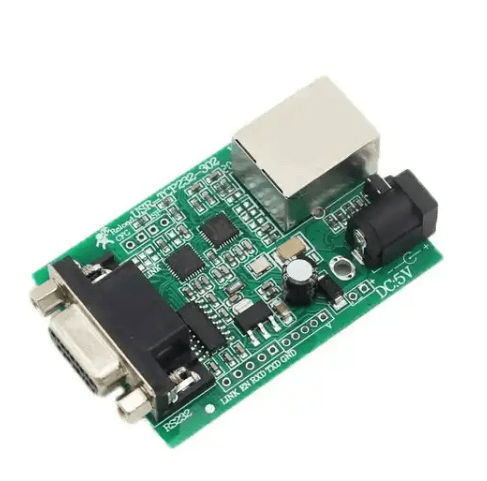
- Interface circuit: including CAN bus interface, RS485 interface, etc., used to communicate with external devices.
- Protection circuit: such as overcurrent protection, overvoltage protection, undervoltage protection, etc., used to protect the safety of the motor and controller.
- Buttons and displays: Such as buttons, LED display, etc., used to set and control the operating status of the motor.
- Other components: such as resistors, capacitors, diodes, crystal oscillators, etc., used to achieve stable operation of the circuit.
The exact number and specifications of these components may vary depending on the specific motor controller design and needs.
Below, Shenzhen Fumax Technology Co., Ltd. will introduce to you the functions, materials and functions of components required for motor controller PCB board assembly.
What role does the microprocessor play in motor controller PCB assembly?
Microprocessor plays a vital role in motor controller assembly. As the brain of the controller, the microprocessor is responsible for processing various signals and control instructions, including sensor signals, PWM signals, etc., to achieve motor control and regulation.
Specifically, the role of the microprocessor in motor controller assembly includes:
- Signal processing: By receiving signals from sensors, the microprocessor can monitor the position, speed and other parameters of the motor in real time, and process these signals into control instructions.
- Control algorithm implementation: The microprocessor can control and adjust the speed, torque and other parameters of the motor by running the control algorithm.
- Communication interface: The microprocessor can communicate with other devices through CAN bus interface, RS485 interface, etc., to realize the transmission and sharing of information.
- Protection function: The microprocessor can monitor the current, voltage and other parameters of the motor. When abnormal conditions occur, protective measures can be taken in time, such as over-current protection, over-voltage protection, etc., to protect the safety of the motor and controller.
- Human-computer interaction: The microprocessor can enable users to set and control the motor through buttons, displays and other components, improving convenience and safety.
Microprocessors play an indispensable role in motor controller assembly, enabling precise control and protection of motors and improving system stability and reliability.
What role does the power circuit play in motor controller PCB assembly?
The power circuit plays a role in providing stable power supply and realizing power conversion in the motor controller PCB assembly. It is an important part of the motor controller, providing the required DC power to the entire controller and ensuring the stability and reliability of the power supply.
Specifically, the role of the power circuit in motor controller PCB assembly includes:
- Power input and output: The power circuit is responsible for converting AC power into DC power, providing stable power for the controller, and at the same time converting electrical energy into voltage and current suitable for the controller.
- Circuit protection: The power circuit has protection functions such as overvoltage, overcurrent, and undervoltage, which can protect the motor controller from overvoltage, overcurrent, etc., and improve the reliability and stability of the controller.
- Filtering and voltage stabilization: The power circuit uses filtering and voltage stabilization technology to minimize noise and interference in the power signal to ensure stable operation of the controller.
- Interface control: The power circuit also has interfaces to connect to other devices, such as sensors, actuators, etc., to realize the transmission and control of electric energy.
The power circuit plays an important role in the motor controller PCB assembly. It provides stable power supply to the entire controller and ensures the reliability and stability of the conversion and transmission of electrical energy.
What role do power devices play in motor controller PCB assembly?
Power devices play a role in controlling and regulating motor power in motor controller PCB assembly. It is one of the core components in the motor controller and can control and adjust parameters such as motor current, voltage and speed.
Specifically, the role of power devices in motor controller PCB assembly includes:
- Current control: Power devices can control the current size and waveform of the motor, thereby controlling and regulating the motor torque.
- Voltage control: Power devices can control the speed and torque of the motor by adjusting the voltage, thereby achieving speed regulation and braking of the motor.
- Protection function: The power device has protection functions such as overcurrent, overvoltage, and undervoltage, which can protect the motor from overcurrent, overvoltage, etc., and improve the reliability and stability of the controller.
- Interface control: Power devices also have interfaces to connect to other devices, such as sensors, actuators, etc., to realize the transmission and control of electric energy.
Power devices play a key role in motor controller PCB assembly. It can control and regulate motor power and ensure stable operation and protection of the motor.
What role do sensors play in motor controller PCB assembly?
Sensors play a role in monitoring the operating status of the motor in the motor controller PCB assembly. The sensor can sense the position, speed, temperature and other parameters of the motor, convert these parameters into electrical signals or digital signals, and transmit them to the motor controller to achieve precise control and regulation of the motor.
Specifically, the role of sensors in motor controller PCB assembly includes:
- Position detection: The sensor can detect the position of the motor, including the position and speed of the motor rotor, thereby achieving precise control of the motor speed and torque.
- Speed detection: The sensor can detect the rotation speed and speed of the motor, thereby achieving precise control and adjustment of the motor speed.
- Temperature detection: The sensor can detect the temperature of the motor, thereby monitoring and protecting the motor’s operating temperature to avoid abnormal situations such as overheating.
- Protection function: The sensor has protection functions such as overcurrent, overvoltage, and undervoltage, which can protect the motor from overcurrent, overvoltage, etc., and improve the reliability and stability of the controller.
- Interface control: The sensor also has interfaces to connect with other devices, such as controllers, actuators, etc., to realize the transmission and control of electric energy.
The sensor plays an important role in the motor controller PCB assembly. It can monitor and perceive the operating status of the motor and transmit the monitoring results to the controller to achieve precise control and adjustment of the motor while protecting the motor and controller. safety.
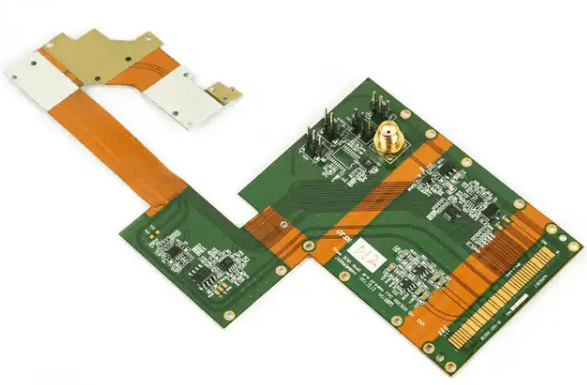
What materials are used for interface circuits in motor controller PCB assembly?
In motor controller PCB assembly, the interface circuit generally uses the following materials:
- Circuit board: PCB board used to make interface circuits, with excellent mechanical properties and dimensional stability.
- Connecting cable: Cables used to connect circuit boards and other equipment, generally using shielded wires or coaxial cables.
- Interface components: electronic components used to connect circuit boards and external devices, such as relays, optocouplers, etc.
- Insulation material: The insulation layer used to protect circuit boards and interface components is generally made of epoxy resin, polyimide and other materials.
- Radiator: used to dissipate heat for circuit boards and interface components. Generally, aluminum or copper radiators are used.
In addition, other materials can also be used, such as electromagnetic shielding materials, thermal conductive materials, etc., depending on specific design requirements and uses.
How should the protection circuit be designed in motor controller PCB assembly?
In the motor controller PCB assembly, the design of the protection circuit is very important, which can ensure the safety and stability of the controller during normal operation. Here are some suggestions for designing protection circuits:
- Reasonable use of multi-layer boards: In the design of multi-layer boards, the inner layer can be used to design protection circuits, such as over-current, over-voltage, under-current, under-voltage and other protection circuits. These protection circuits can comprehensively protect the entire system without affecting the normal operation of other circuits.
- Selection of protection devices: In the design of protection circuits, it is necessary to select appropriate protection devices. For example, you can choose fuses, transient diodes, varistors and other devices to protect the circuit from overcurrent, overvoltage, undercurrent, undervoltage, etc. At the same time, appropriate protection device parameters and specifications need to be selected based on the actual needs of the protection circuit.
- Optimize PCB layout: In PCB layout, the location and layout of the protection circuit need to be considered. In order to better protect the motor controller, the protection circuit can be placed near the core circuit of the controller to ensure comprehensive protection of the entire system.
- Add a protection ring: In order to better prevent external interference and signal coupling interference, a protection ring can be added to the motor controller PCB. The protection ring can effectively reduce the impact of external interference and signal coupling interference on the controller, and can also improve the electromagnetic compatibility performance of the entire system.
- Reasonable use of shielding materials: In the design of motor controller PCB, shielding materials can be reasonably used to improve the anti-interference performance of the entire system. For example, shielding materials can be added around key signal lines to reduce the impact of external interference and signal coupling interference on the controller.
- Consider redundant design: In order to ensure the safety and stability of the motor controller, redundant design can be considered. For example, multiple protection circuits can be added to the system to ensure that when one protection circuit fails, other protection circuits can still work normally.
- Follow relevant standards and specifications: When designing the motor controller PCB, you need to follow relevant standards and specifications. For example, it is necessary to comply with the requirements of EMC, EMS, ESD and other relevant standards and specifications to ensure the safety and stability of the entire system.
In summary, the design of the protection circuit in motor controller PCB assembly requires comprehensive consideration of multi-layer board design, selection of protection devices, PCB layout, adding protection rings, rational use of shielding materials, consideration of redundant design and compliance with relevant standards and specifications and many other aspects. Only in this way can the safety and stability of the motor controller be ensured.
Shenzhen Fumax Technology Co., Ltd. focuses on motor PCB design, assembly, and manufacturing services.
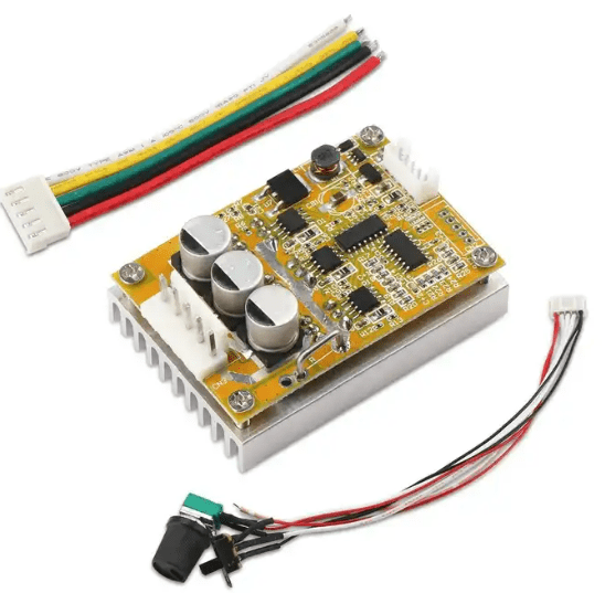
Motor PCB assembly mainly involves laying out and connecting electronic components (such as resistors, capacitors, inductors, etc.) through PCB boards to achieve motor control and driving. The PCB board is the core component of the motor controller, and its quality directly affects the performance and reliability of the motor.
Motor PCB assembly process
The motor PCB assembly process includes the following steps:
- Design and produce PCB board: Design the size, layout and connection method of PCB board according to the requirements and specifications of the motor. Then, use electronic design software to draw and create.
- Selection and procurement of electronic components: According to the design requirements of the PCB board, select appropriate electronic components and purchase them back.
- Layout and connection of components: Lay out the electronic components on the PCB board according to the design requirements, and connect them using wires or welding.
- Debugging and testing: After completing the PCB assembly, debugging and testing are required to ensure that the performance and reliability of the motor controller meet the requirements.
- Quality inspection and acceptance: Inspect and accept the quality of PCB assembly to ensure that every link meets quality requirements.
During motor PCB assembly, you need to pay attention to the following points:
- The design of the PCB board should be reasonable, the layout should be compact, and the wiring should be simple and clear to improve the performance and reliability of the electronic control system.
- The selection of electronic components must meet the design requirements, the quality must be reliable, and the quantity must be accurate.
- The layout of components must be reasonable, and the connections must be firm and reliable to avoid welding, open circuits, etc.
- During the debugging and testing process, problems must be discovered and solved in time to ensure the stability and reliability of the electronic control system.
- Quality inspection and acceptance must be strictly controlled to ensure that every link meets quality requirements to ensure the quality and performance of the final product.
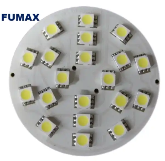
LED display and button function assembly in motor controller PCB assembly
In the assembly of motor controller PCB, the assembly of LED display and button functions is also a very important link. The following are specific steps and precautions:
- Assembly of LED display:
- Confirm the model and specifications of the LED display, as well as its location and connection method on the PCB board.
- Prepare the corresponding LED display driver circuit and connect it to the PCB board.
- Follow the instructions of the LED display for assembly and debugging to ensure that the display effect is normal.
- Assembly of button functions:
- Confirm the model and specifications of the button, as well as its location and connection method on the PCB board.
- Prepare the corresponding key switch circuit and connect it to the PCB board.
- According to the design requirements, connect the key switch to the control circuit to realize the corresponding control function.
When assembling the LED display and button functions, you need to pay attention to the following points:
- The models and specifications of the LED display and buttons must meet the design requirements, and the quantities must be accurate.
- The installation position of the LED display screen and buttons must be accurate, and the connection must be firm and reliable.
- The display effect of the LED display screen must be debugged and tested to ensure that the display effect is normal.
- The connection of the key switch must be firm and reliable to avoid poor contact and other phenomena.
- During the assembly process, pay attention to protecting the PCB board and other electronic components to avoid damage or contamination.
In the assembly of motor controller PCB, the assembly of LED display and button functions is a very important link. It is necessary to carefully carry out assembly and debugging in accordance with the design requirements to ensure that the performance and reliability of the electronic control system meet the requirements.
Introduction to the assembly of resistors, capacitors, diodes and crystal oscillators in motor controller PCB assembly
In motor controller PCB assembly, the assembly of electronic components such as resistors, capacitors, diodes, and crystal oscillators is also a very important link. The following are specific steps and precautions:
- Assembly of resistor:
- Confirm the model and specification of the resistor, as well as its location and connection method on the PCB board.
- Prepare the corresponding resistors and connect them to the PCB board.
- Pay attention to the connection according to the design requirements to ensure that the connection is firm and reliable.
- Assembly of capacitor:
- Confirm the model and specifications of the capacitor, as well as its location and connection method on the PCB board.
- Prepare the corresponding capacitor and connect it to the PCB board.
- Pay attention to the connection according to the design requirements to ensure that the connection is firm and reliable.
- Assembly of diode:
- Confirm the diode model and specifications, as well as its location and connection method on the PCB board.
- Prepare the corresponding diode and connect it to the PCB board.
- Pay attention to the connection according to the design requirements to ensure that the connection is firm and reliable.
- Assembly of crystal oscillator:
- Confirm the model and specifications of the crystal oscillator, as well as its location and connection method on the PCB board.
- Prepare the corresponding crystal oscillator and connect it to the PCB board.
- Pay attention to the connection according to the design requirements to ensure that the connection is firm and reliable. Generally, the core frequency of the crystal oscillator can be changed by adjusting the value of the matching capacitor.
When assembling these electronic components, you need to pay attention to the following points:
- The model and specification must meet the design requirements, and the quantity must be accurate.
- The installation position must be accurate and the connection must be firm and reliable.
- During the assembly process, pay attention to protecting the PCB board and other electronic components to avoid damage or contamination.
- For some sensitive electronic components, such as crystal oscillators, attention should be paid to protection and debugging to ensure that their accuracy and stability meet the requirements.
In the assembly of motor controller PCB, the assembly of electronic components such as resistors, capacitors, diodes, and crystal oscillators is a very important link. It is necessary to carefully carry out assembly and debugging in accordance with the design requirements to ensure that the performance and reliability of the electronic control system meet the requirements.
The best motor controller PCB assembly manufacturer in China
Shenzhen Fumax Technology Co., Ltd. provides one-stop services such as SMT patching, DIP welding, circuit board PCBA design and custom development, software programming, component procurement, electronic assembly testing and painting.
Provide diversified OEM and ODM services to domestic and foreign customers.
PCB manufacturing and PCB assembly factory equipment: fully automatic solder paste printing machine, SPI, multiple high and medium speed placement machines, 10 temperature zone reflow soldering, wave soldering, selective wave soldering, X-Ray inspection, AOI equipment, automatic soldering machine etc.
Production product quality inspection: comply with ISO90001, CE, FCC, UL, ROHS, TS16949 standards.
Service product application areas: MCU, consumer electronics, automotive electronics, remote communications, industrial control, smart cities, Internet of Things, vehicle systems, smart homes, and medical equipment.
Fumax is the world’s leading manufacturer of multi-layer circuit boards and one of the largest PCB manufacturing and PCB assembly companies in China. The headquarters is located in Shenzhen, China. Please contact us to learn more.