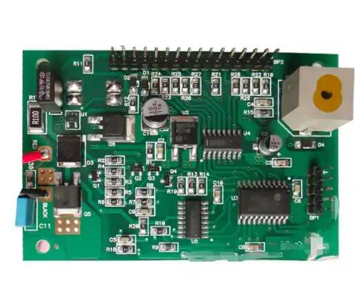
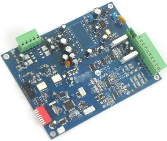
Motor drive unit PCB assembly is an important link in solar trackers. A solar tracker is a system that can automatically track the movement of the sun and adjust the angle of the solar panel in real time by controlling the rotation of the motor, thereby improving the collection efficiency of solar energy.
Therefore, the PCB assembly of the motor drive unit has a crucial impact on the performance and stability of the entire solar tracker.
The purpose of motor drive unit PCB assembly
The main purpose of motor drive unit PCB assembly is to integrate motor drive chips, sensors, power supplies and other electronic components onto the PCB board, and to achieve motor drive control and protection functions through reasonable layout and design. This PCB assembly can improve the stability and efficiency of solar trackers while reducing system power consumption and cost.
Design points of motor drive unit PCB assembly
Component layout
In motor drive unit PCB assembly, the layout of components is one of the key factors affecting system performance and stability. In order to achieve efficient heat dissipation and stable circuit performance, it is necessary to reasonably arrange the positions of chips, resistors, capacitors and other components, and leave appropriate space for wiring and welding.
Circuit protection
The motor drive circuit needs to have overcurrent, overvoltage, undervoltage and other protection functions to prevent damage to the motor and control circuit caused by system faults. Therefore, corresponding protective components and circuits, such as fuses, diodes, resistors, etc., need to be added to the PCB design to protect the circuit.
Signal transmission
The motor drive unit needs to transmit signals with other components such as sensors and control units, so the signal transmission path and interface design need to be taken into consideration in PCB design. In order to ensure signal stability and anti-interference, appropriate transmission cables and interface protocols need to be used for connection.
Power supply design
Power supply design is a very important link in the PCB assembly of the motor drive unit. In order to ensure the stable operation of the motor and the power consumption control of the entire system, it is necessary to select an appropriate power chip and circuit design, and take into account the heat dissipation and noise issues of the power supply.
Process flow of PCB assembly of motor drive unit
- Prepare materials: including PCB board, electronic components, solder paste, soldering station, etc.
- Layout design: Place electronic components in a reasonable position and leave appropriate space for wiring and welding.
- Wiring design: Carry out wiring design for the PCB board based on the circuit schematic diagram and component layout.
- SMD welding: Weld the electronic components to the PCB board according to the layout.
- Inspection and debugging: Inspect and debug the welded PCB board to ensure the correctness and stability of the circuit.
- Packaging and delivery: Pack the qualified PCB board and deliver it to the customer or install it on the solar tracker.
Things to note when assembling the PCB of the motor drive unit
During the welding process, it is necessary to avoid the occurrence of virtual welding, short circuit and other phenomena to ensure the welding quality.
Special protection measures are required for some components that are easily affected by temperature and humidity.
During the installation process, ensure the flatness and firmness of the PCB board to avoid loosening or falling off due to vibration or impact.
During the debugging process, the circuit needs to be comprehensively inspected and tested to ensure the correctness and stability of the circuit.
Summary
The motor drive unit PCB assembly is one of the important links in the solar tracker, and its performance and stability directly affect the performance and reliability of the entire system. Therefore, when assembling the motor drive unit PCB, it is necessary to fully consider the performance requirements of the circuit and the characteristics of the components, and strictly follow the process flow to ensure the performance and stability of the entire system.