The motor controller is the core component of the motor drive system and is responsible for controlling the start, stop, speed and direction of the motor.
MCU (microcontroller) is a common motor controller. It has the advantages of small size, low power consumption, and high reliability, and is widely used in various motor drive systems. This article will conduct a detailed analysis of the design principles of motor controller MCU.
MCU basic structure and functions
MCU is a microcomputer based on integrated circuits, which integrates multiple functional modules such as CPU, memory, timer/counter, input and output interfaces, etc. The basic structure of MCU is as follows:
CPU
The core component of MCU is responsible for executing program instructions and controlling the work of other modules.
memory
Used to store program code and data, it is divided into two types: ROM (read-only memory) and RAM (random access memory).
Timer/Counter
Used to generate timing signals and control counter values, and can be used to implement functions such as timers and counters.
Input and output interface
Used to connect the communication between MCU and external devices. Common interfaces include SPI, I2C, UART, etc.
In addition, MCU also has the following functions:
digital signal processing
MCU can process digital signals, such as AD conversion, DA conversion, etc.
Communication Interface
MCU has interfaces for communicating with external devices, such as CAN bus, LIN bus, etc.
Program download and debugging
MCU can download and debug programs through the serial port or other methods.
Motor controller MCU design principles
The design principle of the motor controller MCU is mainly to control the motor through the combination of hardware circuits and software programs. The following will conduct a detailed analysis from two aspects: hardware circuit and software program.
Hardware circuit design
The hardware circuit design of the motor controller MCU mainly includes power circuit, drive circuit, sampling circuit, protection circuit and other parts.
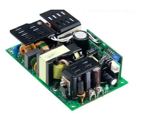
- Power circuit: Provide stable power supply for MCU and other circuits, generally using switching power supply or linear regulated power supply.
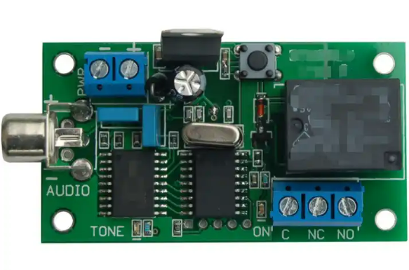
- Drive circuit: The drive circuit is the bridge between the MCU and the motor. It is responsible for converting the control signal output by the MCU into a power signal that can drive the motor. Common drive circuits include H-bridge drive circuits and PMSM drive circuits.
- Sampling circuit: The sampling circuit is responsible for real-time monitoring and sampling of the motor’s current, voltage and other parameters, and feeding the sampling results back to the MCU. Common sampling circuits include current sampling circuits and voltage sampling circuits.
- Protection circuit: The protection circuit is a circuit used to protect the MCU and other circuits from overcurrent, overvoltage, overtemperature, etc. Generally include fuses, overcurrent protectors, temperature sensors and other components.
software programming
The software program of the motor controller MCU is the core part of realizing motor control. It mainly includes the following modules:
- Main program module: The main program module is the entrance to the entire software program. It is responsible for initializing each module and calling other program modules to realize motor control. The main program module generally includes system initialization module, interrupt processing module, etc.
- Control algorithm module: The control algorithm module is the core part of realizing motor control. It uses certain control algorithms (such as PID algorithm, fuzzy control algorithm, etc.) based on the motor parameters (such as current, voltage, etc.) fed back by the sampling circuit. Calculate the control signal to the motor to control the speed and direction of the motor.
- Communication module: The communication module is responsible for data transmission and communication between the MCU and other devices. For example, control signals can be transmitted to other devices or related data obtained from other devices through the CAN bus or LIN bus.
- Fault diagnosis module: The fault diagnosis module is responsible for detecting and diagnosing faults that occur during motor operation. Once a fault occurs, appropriate protective measures are taken in a timely manner to avoid damage to the motor and other circuits. Common fault diagnosis methods include fault code reading, fault type judgment, etc.
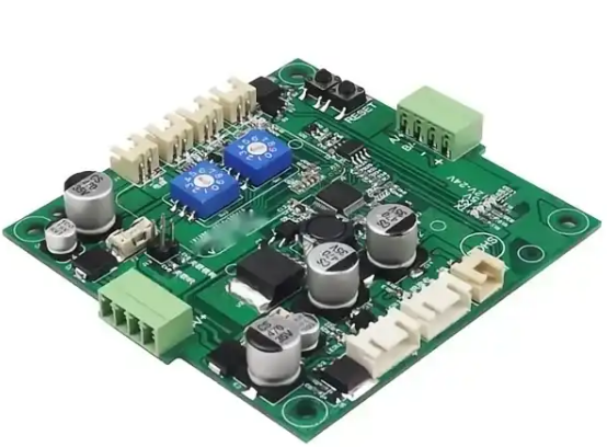
Motor controller MCU custom design manufacturer
Fumax is a custom motor controller MCU design manufacturer in China. It has a professional technical team and advanced equipment to provide customers with personalized motor controller MCU design services.
The manufacturer has rich industry experience and can provide customized solutions based on customer needs and product characteristics.
During the design, manufacturers will fully consider the performance, control accuracy, reliability and other factors of the motor to ensure that the designed motor controller MCU can meet the specific needs of customers.
In addition, the manufacturer also provides technical support and after-sales service to ensure that customers receive timely technical support and solutions during use.