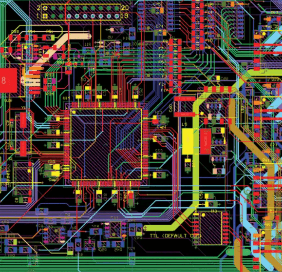
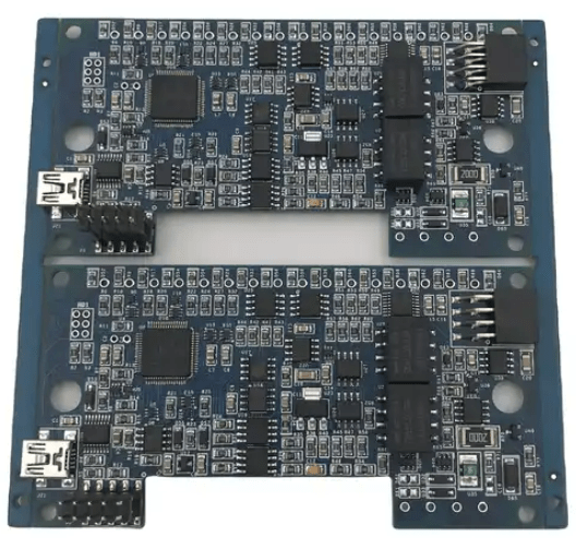
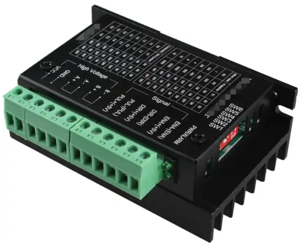
The motor PCB assembly design solution is a design solution to improve the manufacturability of the motor PCBA. Solve problems such as motor PCB layout design, motor PCB manufacturing, motor PCB assembly, pad design, and electronic component layout according to customer needs.

The motor PCB assembly design solution mainly includes the following steps:
- Clarify the requirements and parameters of the motor drive: including power, voltage, current, control method, etc., and determine the overall functions and required interfaces of the motor drive according to the needs.
- Determine the size and shape of the PCB: Determine the size and shape of the PCB according to the size requirements of the motor drive and the external connection interface.
- Layout planning: Carry out overall layout planning based on the location and connection relationships of power supplies, signal lines, radiators and other components. Reasonably arrange the placement of components, reduce wiring length, and reduce electromagnetic interference.
- Electromagnetic compatibility design: The motor control circuit should meet electromagnetic compatibility standards, taking into account electromagnetic interference sources, electromagnetic coupling paths and electromagnetic interference affecting or receiving devices to reduce the sensitivity of the circuit to electromagnetic interference.
- Consider thermal design: For some motor PCBs that require long-term operation or high power consumption, thermal design needs to be considered. Thermal design mainly ensures that the temperature of the PCB will not be too high during operation by optimizing PCB materials, component placement, and heat dissipation methods, thereby ensuring its stability and reliability.
- Determine the connection method: Determine the PCB connection method according to the design specifications and the connection method between components. Common connection methods include welding, crimping, screw connections, etc.
- Draw PCB diagram: Draw PCB diagram according to design specifications and component selection. The PCB diagram should clearly reflect the size of the circuit board, the location of the components, the connection method and other information.
- Review the PCB diagram: After drawing the PCB diagram, it needs to be reviewed to ensure the correctness and reliability of the design. The audit should include inspections of electrical performance, mechanical structure, signal transmission, etc.
- Make PCB: Make PCB based on the approved PCB drawing. The production process should be carried out in strict accordance with the process requirements to ensure the quality and reliability of the PCB.
- Assemble components: Assemble the selected components according to the PCB diagram. The assembly process should be carried out in strict accordance with the process requirements to ensure the connection method of components and the reliability of signal transmission.
- Test PCB: After assembly, the PCB needs to be tested to ensure the reliability of its electrical performance and mechanical structure. Testing should include functional testing, withstand voltage testing, temperature testing, etc.

The above is the solution for motor PCB assembly design. The specific steps may be different in different situations and need to be adjusted and optimized according to the specific situation.

Fumax is equipped with high-precision imported equipment, including fully automatic solder paste printing machines, SPI, 10-temperature zone reflow soldering, wave soldering, selective wave soldering, AOI equipment, multiple high- and medium-speed placement machines, X-Ray detection, automatic Soldering machine and so on.