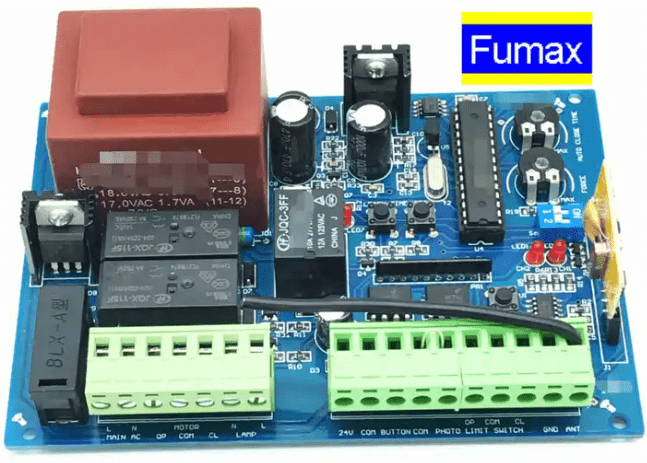
Brushless DC motor controller PCB board assembly process
The brushless DC motor controller PCB assembly and manufacturing process includes raw material preparation, printing board production, component production, electroplating, drilling, assembly and testing.
- Preparation stage
Before starting assembly, you need to prepare all necessary raw materials, including PCB boards, electronic components, heat sinks, gaskets, insulating sleeves, etc. At the same time, you also need to prepare assembly tools, such as screwdrivers, welding tools, cleaning agents, etc.
- PCB board design
The design of PCB board is the basis of the entire assembly process. According to the control requirements of the brushless DC motor, use professional PCB design software to draw the design drawing of the PCB board. During the design process, factors such as circuit layout, component arrangement, power supply and signal distribution need to be considered to ensure that the function and performance of the PCB board meet the requirements.
- Electronic component welding
Weld the electronic components to the PCB board according to the design drawing of the PCB board. During the welding process, you need to pay attention to the following points:
The components must be arranged correctly, and there should be no mis-soldering or missing soldering.
The welding quality should be high, and the solder joints should be smooth and full to avoid false or false welding.
The contact between the components and the PCB board should be good to avoid poor contact.
- Install the heat sink
The brushless DC motor controller generates a lot of heat when working, so it is necessary to install a heat sink to dissipate heat. Fix the heat sink to the PCB board with screws, making sure that the heat sink is in good contact with the PCB board. At the same time, you need to pay attention to the following points when installing the heat sink:
The installation position of the heat sink must be correct, and there should be no deviation or missing installation.
The screws should be tightened to ensure that the heat sink is in close contact with the PCB board.
The surface of the heat sink should be kept clean and free of dirt or foreign matter.
- Install gaskets and insulating sleeves
Add thermally conductive and insulating gaskets and insulating plastic sleeves for screws between the heat sink and the PCB board. The gasket can increase the thermal conductivity between the heat sink and the PCB board, and the insulating sleeve can prevent short circuits caused by poor contact between the screws and the PCB board. You need to pay attention to the following points during the installation process:
The installation positions of gaskets and insulating sleeves must be correct, and no misinstallation or missing installation should occur.
The materials of gaskets and insulating sleeves must meet the requirements and do not use inferior materials.

The gasket and insulating sleeve must be firmly fixed and not loose.
- Testing and debugging
After completing the assembly, perform testing and debugging to ensure that the brushless DC motor controller is working properly. Testing and debugging include the following aspects:
(1). Power supply test: Check whether the voltage and current of the power supply meet the requirements and are stable.
(2). Component function test: Check whether the function of each electronic component is normal and meets the design requirements.
(3). Control system test: Check whether the logical relationship of the control system is correct and whether it can accurately control the operation of the brushless DC motor.
(4). Protection function test: Check whether the protection function is working normally, such as overheating protection, overload protection, etc.
(5). Performance test: Test whether the performance indicators of the brushless DC motor, such as speed, torque, efficiency, etc., meet the requirements.
(6). Environmental adaptability test: Test the working stability of the brushless DC motor controller in different environments.
(7). Reliability test: Test whether the reliability indicators of the brushless DC motor controller, such as working time, lifespan, etc., meet the requirements.
- Quality inspection and records
Conduct quality inspection and records for each testing and debugging link to ensure that each link meets the requirements. At the same time, the entire assembly process is summarized and evaluated to continuously optimize and improve production efficiency and quality levels.