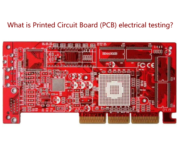
PCB electrical testing is the process of testing the electrical performance of a printed circuit board (PCB), aiming to ensure that the PCB can work properly and comply with relevant specifications and requirements during design, manufacturing and actual use. PCB electrical testing standards include international standards and national standards.
Before understanding the process of PCB electrical testing, we first understand the composition and process flow of PCB electrical testing.
- What are the components of electrical PCB testing?
- What are the types of PCB electrical testing?
- What is the process of PCB electrical testing?
- To what standard are electrical tests used to ensure the integrity of PCBs (Printed Circuit Boards)?
- What is DFM for printed circuit board electrical testing?
- What is the purpose of PCB electrical testing?
- Who is responsible for DFM during PCB electrical testing?
- Importance of DFM in PCB manufacturing testing?
- Why do we need to conduct electrical testing on PCB after producing it?
- What are the eligibility criteria for PCB electrical testing? What are the PCB inspection standards?
- Can electrical testing be performed on electronic products?
- What basic technologies and methods does electronic measurement technology include?
- What technical capabilities should a PCB electrical test engineer have?
- What are the functions of a PCB electrical test engineer?
- PCB electrical testing factory
What are the components of electrical PCB testing?
The components of electrical PCB testing mainly include the following aspects:
- Test equipment and fixtures: used to provide necessary power and signals during the test process, as well as to ensure correct connections and stable test conditions.
- Test procedures and standards: In order to ensure that all tests are conducted according to unified standards, detailed test procedures need to be written to clarify test steps, test methods and qualification standards.
- Test data analysis: Through data analysis of test results, problem areas can be identified and corresponding improvement measures can be taken.
What are the types of PCB electrical testing?
Types of PCB electrical testing can be classified based on specific needs. Here are some common types:
- Functional test: Check whether the functions of the PCB are normal, such as whether switches, LEDs, etc. can work normally.
- Performance test: measure whether the performance parameters of the PCB, such as resistance, capacitance, inductance, etc., meet the design requirements.
- Connectivity test: Check whether the connection on the PCB is correct and stable, such as soldering quality, pin connection, etc.
- Signal integrity test: Verify whether the signal transmission on the PCB is correct and whether there are interference, distortion and other problems.
What is the process of PCB electrical testing?
The PCB electrical testing process usually includes the following steps:
- Prepare test equipment: Prepare the required test equipment and fixtures to ensure the stability and consistency of the test conditions and environment.
- Develop a test plan: According to product requirements and specifications, develop a detailed test plan, including test items, test methods, qualification standards, etc.
- Install and connect the test equipment and fixtures: Install and connect the test equipment and fixtures to the circuit board under test to ensure the stability and correctness of the connection.
- Execute tests: According to the test plan, execute various tests and record test data and results.
- Data analysis: Analyze and process test data, identify problem areas and potential failures, and give corresponding suggestions and improvement measures.
- Report writing and document maintenance: Write test reports and documents, record test results and problem solutions, and maintain related documents and data.
- Follow-up: Based on the test results and improvement measures, make corresponding modifications and improvements to improve product quality and reliability.
To what standard are electrical tests used to ensure the integrity of PCBs (Printed Circuit Boards)?
Electrical testing is usually based on industry standards and company internal standards to ensure the integrity of the PCB. Industry standards such as IPC-A-600F (Acceptable Conditions for Electronic Components) provide specific requirements and acceptance criteria for electrical testing. The company’s internal standards are formulated based on the characteristics and needs of its own products to ensure product quality and reliability.
What is DFM for printed circuit board electrical testing?
DFM is the abbreviation of Design For Manufacturability, which refers to a design method that considers manufacturing process and manufacturability when designing PCB. Electrical testing is an important aspect of DFM. It involves testing the connectivity, electrical parameters, power consumption, signal integrity and functionality of electronic components and circuits on the PCB to ensure that the PCB can comply with the design during the actual manufacturing process. requirements and manufacturing standards.
What is the purpose of PCB electrical testing?
The purpose of PCB electrical testing is to verify whether the function and performance of electronic components and circuits on PCB meet design requirements and specifications to ensure the reliability and performance of the final product. Through electrical testing, problems in circuit design can be discovered and repaired, production quality can be ensured, product reliability can be improved, safety can be ensured, etc.
Who is responsible for DFM during PCB electrical testing?
During the PCB design stage, DFM is usually the responsibility of the PCB designer or electronic engineer. They need to consider manufacturing processes and manufacturability to ensure that the designed circuit board can be manufactured successfully and meet all necessary quality and reliability standards. After manufacturing is complete, final electrical testing is required to ensure that the board functions and performs as required.
Importance of DFM in PCB manufacturing testing?
DFM is very important in PCB manufacturing testing. It helps designers ensure that the circuit boards they design are manufacturable and avoid problems during the manufacturing process. At the same time, DFM can also improve production efficiency, reduce costs, reduce scrap rates, etc. During final electrical testing, DFM can also help identify and resolve potential issues, ensuring product quality and reliability.
Why do we need to conduct electrical testing on PCB after producing it?
Electrical testing is performed after PCB production to ensure that each board meets specific electrical performance standards. These tests include checking connectivity, measuring electrical parameters such as resistance, capacitance and inductance, and verifying signal integrity and functionality. Through these tests, potential problems can be discovered and repaired in time to avoid failures or adverse consequences during subsequent use. At the same time, these test results can also be used for quality control and product reliability assessment purposes.
What are the eligibility criteria for PCB electrical testing? What are the PCB inspection standards?
PCB inspection standards can be divided into two major categories: international standards and national standards.
international standards
International standards are developed by international organizations and are applicable to PCB production and use in different countries and regions.
For example, IPC (International Printed Circuit Association) has developed a series of IPC standards, including IPC-A-600 (Printed Circuit Board Appearance Acceptance Standard), IPC-6012 (Rigid Printed Circuit Board Performance Specification), etc.
National standard
National standards are formulated by each country based on its own actual conditions and are applicable to PCB production and use in its own country or region. For example, China has formulated a series of GB/T (national standards) and SJ/T (electronics industry standards), including GB/T 4677.1 (General Technical Conditions for Printed Boards), SJ/T 11364 (Environmentally Friendly Product Labeling for Printed Boards) requirements) etc.
Of course, in addition to these two categories, there are also some industry standards, enterprise standards, customer standards, etc., which are formulated for specific fields or needs.
PCB inspection standards are of great significance to ensure the quality and safety of PCBs. By following PCB inspection standards, you can improve the consistency and interchangeability of PCBs, facilitate production and use, reduce the defective and repair rates of PCBs, save costs and time, avoid electronic equipment failures or accidents caused by PCBs, and protect personnel and equipment. , improve the market competitiveness and credibility of PCB, and increase customer satisfaction. Jiepei always puts user experience first, continuously improves product yield rate on the production side, and provides high-quality products.
Can electrical testing be performed on electronic products?
Yes, electrical testing of electronic products can be performed. Electrical testing is an important part of evaluating the performance and quality of electronic products. Through testing, potential problems can be discovered and solved, and the reliability and performance of the product can be improved. Electrical testing includes many types, such as connectivity testing, electrical parameter testing, power consumption testing, signal integrity testing, etc., covering different aspects and performance indicators of the circuit board. When conducting electrical testing, it is necessary to use professional testing equipment and fixtures and operate in accordance with the testing plan and specifications to ensure the accuracy and reliability of the testing.
What basic technologies and methods does electronic measurement technology include?
Electronic measurement technology includes the following basic technologies and methods:
- Voltage measurement: Measure the voltage value in the circuit by using a measuring instrument such as a voltmeter or multimeter to ensure that the voltage is within the specified range.
- Current measurement: By using measuring instruments such as ammeters or multimeters, measure the current value in the circuit to ensure that the current is within the specified range.
- Resistance measurement: By using measuring instruments such as resistance meters or multimeters, measure the resistance value in the circuit to ensure that the resistance is within the specified range.
- Capacitance and inductance measurement: By using corresponding measuring instruments, measure the capacitance and inductance values in the circuit to ensure that it meets the design requirements.
- Use of signal generator and oscilloscope: Signal generator is used to generate various signals, and oscilloscope is used to observe and analyze the waveform and parameters of the signal in order to conduct signal integrity and performance testing.
- Use of network analyzer: Network analyzer is used to measure the frequency response and impedance characteristics of circuit components for circuit analysis and fault diagnosis.
What technical capabilities should a PCB electrical test engineer have?
PCB electrical test engineers should have the following technical capabilities:
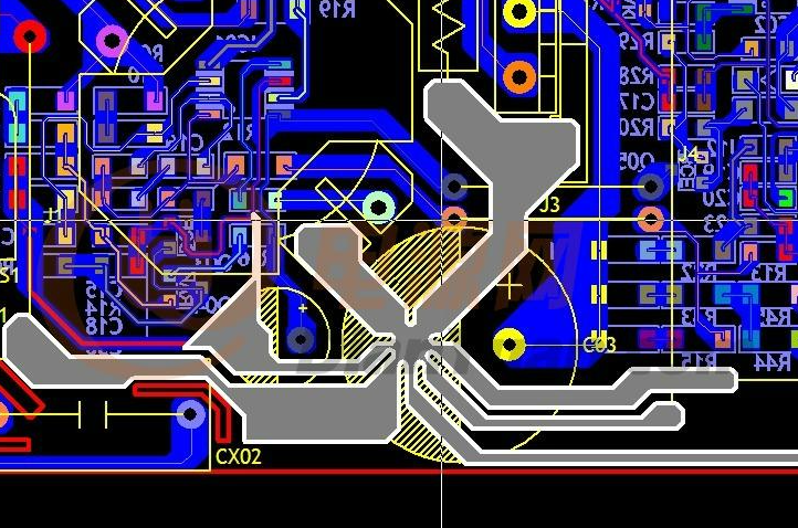
- Basics of circuit design: PCB electrical testing engineers need to understand the basic principles and design methods of circuits, and be able to read circuit diagrams and circuit board design documents.
- Electronic measurement technology: PCB electrical testing engineers need to master the basic technologies and methods of electronic measurement, such as the measurement of voltage, current, resistance, capacitance, inductance, etc., as well as the use of instruments such as signal generators and oscilloscopes.
- Automated testing technology: PCB electrical testing engineers need to understand the basic principles and methods of automated testing and be able to use automated testing software and hardware for testing.
- PCB design software operation ability: PCB electrical testing engineers need to master the operation and use of common PCB design software, such as Altium Designer, Eagle, etc.
- Fault diagnosis and repair capabilities: PCB electrical testing engineers need to be able to diagnose and repair circuit board faults based on test results, and be able to make suggestions for improvements.
- Good communication and coordination skills: PCB electrical testing engineers need to maintain good communication and coordination with designers, manufacturing engineers and other personnel to ensure the smooth progress of testing work.
What are the functions of a PCB electrical test engineer?
The functions of PCB electrical test engineers mainly include the following aspects:
- Responsible for formulating and executing PCB electrical test plan to ensure test progress and quality.
- Conduct functional and performance tests on PCBs, record and analyze test data to ensure the accuracy and reliability of test results.
- Make suggestions for improvements, assist designers and manufacturing engineers in solving problems, and improve product quality and reliability.
- Write and maintain test reports and documents to record test results and problem solutions.
- Responsible for the maintenance and upkeep of testing equipment and fixtures to ensure the stability and consistency of testing conditions.
- Assist other departments to carry out related work, such as production site technical support, product acceptance, etc.
PCB electrical testing factory
Fumax is a PCB manufacturer in China, providing one-stop services such as PCB manufacturing raw material procurement, PCB design, electronic design, reverse engineering, PCB assembly, and PCBA customization.